

Every construction professional has stood over a drawing set and mixed up a section with an elevation at least once. It happens because the two drawings look related on paper but answer completely different questions.
A section drawing cuts through a building to show what is happening inside its walls, floors, and structure. An elevation drawing shows the outside face of a building exactly as a person standing in front of it would see it. In simple terms, a section shows what you cannot see, and an elevation shows what you can.
Getting this distinction right matters on site. Architects, structural engineers, quantity surveyors, masons, and MEP contractors all read these drawings differently depending on what they need from them. Confuse the two and you risk misreading a wall thickness, a finish level, or a structural connection that was never meant to be read that way.
This post breaks down what each drawing actually shows, how to read them correctly, and why every professional on a construction team needs to understand both.
Quick Answer: A section drawing is a vertical cut through a building showing internal construction, floor levels, and structural detail, while an elevation drawing shows the external face of a building without cutting through it. Sections tell you how a building is built; elevations tell you how it looks.
What Is a Section Drawing?
A section drawing is produced by imagining a vertical cut through the building, then drawing what you would see if that slice was pulled apart and viewed from the side.
That cut line is marked on the floor plan, usually labelled A-A or B-B, and it tells you exactly where the section was taken. Once you know the cut line, the section drawing shows you floor-to-floor heights, foundation depth, roof pitch, slab thickness, wall construction, and how different building elements connect vertically.
The truth is, a section is the drawing that tells you the most about how a building actually stands up. It is where structural engineers confirm beam depths, where architects show ceiling heights and staircase rise, and where contractors check damp-proof course levels and lintel positions.
A good section drawing typically includes:
- Finished floor levels (FFL) and finished ceiling levels
- Foundation type and depth below ground level
- Wall thickness and material build-up
- Roof structure and pitch angle
- Staircase geometry, including rise and going
- Insulation, waterproofing, and finishes layers
What Is an Elevation Drawing?
An elevation drawing shows one face of a building as seen from directly outside it, without any cutting through the structure. If a section shows the inside of a building, an elevation shows its skin.
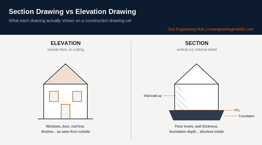
Buildings are normally drawn with four elevations, one for each face: front, rear, and two sides. Depending on site orientation, these are often labelled North, South, East, and West elevation instead, which is the more accurate way to reference them on a working drawing set.
Elevations communicate the architectural character of a building. They show window and door positions, roof lines, external finishes, parapet heights, and how the building will actually look once complete. Masons use elevations to confirm opening positions and finish levels. Electricians and other MEP contractors use them to locate external fittings such as lighting points, meter boxes, and downpipes.
Honestly, elevations are the drawings most people outside construction actually understand at a glance, because they look like the finished building. That is exactly why they are used in client presentations and planning applications.
Section vs Elevation: The Key Differences
| Feature | Section Drawing | Elevation Drawing |
|---|---|---|
| What it shows | Internal cut through the building | External face of the building |
| Purpose | Reveals construction and structure | Reveals appearance and finishes |
| Drawn by cutting | Yes, along a marked section line | No, viewed straight on |
| Key information | Floor levels, wall build-up, foundation depth, roof structure | Window/door positions, external finishes, roof lines, heights |
| Main users | Structural engineers, architects, site supervisors | Architects, masons, electricians, clients |
| Typical scale | 1:50 or 1:20 for detail sections | 1:100 or 1:50 |
How to Read Each Drawing Correctly on Site
Reading a drawing correctly starts with checking the title block, not the picture. The title block tells you the scale, the drawing number, the revision date, and which section line or elevation face you are looking at. A drawing without a checked title block has already cost someone time on site before the tape measure even comes out.
For a section drawing, start by locating the cut line on the corresponding floor plan. This tells you exactly where the building was sliced and what you should expect to see. Then work from the foundation upward, level by level, cross-checking each floor level against the structural drawings.
For an elevation drawing, start by confirming which face you are looking at using the compass orientation on the site plan. Then check opening positions against the floor plan, since a door shown on an elevation must line up exactly with the same door on the plan.
Under the Kenya Building Code 2024, architectural and structural drawings submitted for approval must be produced to a consistent scale and clearly cross-referenced between plans, sections, and elevations. This requirement exists precisely because misreading between drawing types is one of the most common causes of construction disputes and rework on site. ISO 128, the international standard for technical drawing conventions, also governs how section cut lines, hatching, and elevation labelling should appear, so professionals working across international clients will recognize the same symbols regardless of where the drawing was produced.
Scale is another detail that trips people up on site. A section drawn at 1:20 will show far more construction detail, such as insulation layers and flashing, than the same section drawn at 1:50 for general coordination. Before scaling anything off a printed drawing with a ruler, always confirm the stated scale in the title block, because drawings are frequently printed or shared at a reduced size that no longer matches the original scale notation. When in doubt, use the written dimensions on the drawing rather than measuring the paper directly.
Common Mistakes When Interpreting Section and Elevation Drawings
| Mistake | Why It Happens | How to Avoid It |
|---|---|---|
| Reading wall thickness from an elevation | Elevations do not show wall build-up, only the outer face | Always check wall thickness on the section or plan |
| Assuming floor levels from an elevation | Elevations show height but not internal floor-to-floor detail | Cross-check floor levels (FFL) on the section drawing |
| Ignoring the section cut line | The section only makes sense in the context of where it was cut | Locate the A-A or B-B line on the plan before reading the section |
| Using the wrong elevation for orientation | Confusing front and rear elevations on an irregular site | Confirm compass direction against the site plan first |
| Skipping the drawing revision date | Working from an outdated drawing that was later revised | Always check the title block revision number before use |
Why Every Construction Professional Needs Both
A building cannot be built correctly from elevations alone, and it cannot be sold or approved from sections alone. The two drawings work together, and that is the point most students miss when they are first learning to read a drawing set.
An architect uses elevations to design and present the building, then relies on sections to prove the design actually works structurally and dimensionally. A structural engineer lives mostly in the section, confirming beam depths and slab thickness, but still needs the elevation to understand where openings will affect load paths. A quantity surveyor measuring external wall finishes needs the elevation for area, but needs the section to understand material build-up and thickness for accurate quantities.
On a real site in Kenya, this shows up constantly. A mason building a parapet wall needs the section to get the correct height above roof level, but needs the elevation to get the correct finish and coping detail. Skipping either drawing produces a wall that is either the wrong height or the wrong finish, and both mistakes cost money to correct.
Electricians and plumbers benefit from the same discipline. A plumber routing a downpipe needs the elevation to confirm where it discharges at ground level, but needs the section to confirm it does not clash with a beam or slab edge on its way down. This is exactly why coordinated drawing sets exist, and why every professional on a project, not just the architect, should be comfortable moving between a section and an elevation without needing someone else to translate it for them.
Frequently Asked Questions
Q: Can a section drawing and an elevation drawing show the same wall?
Yes, but they show different information about it. The elevation shows the outer face of that wall, including openings and finishes, while the section shows what the wall is actually made of, layer by layer, from the outside finish through to the internal plaster.
Q: How many elevations does a typical building drawing set include?
Most residential and commercial buildings are drawn with four elevations, one for each face of the building. Complex or irregular buildings sometimes need additional elevations to fully describe every visible face, especially where the building has more than four distinct sides.
Q: Why do some sections look different even for the same building?
Because a building can be cut at multiple locations to reveal different construction details. A section through a staircase looks completely different from a section through a straight external wall, even though both belong to the same building and the same drawing set.
Conclusion
A section drawing and an elevation drawing are not interchangeable, and mixing them up on site leads to real construction errors. Sections show you how a building is built from the inside out. Elevations show you how it looks from the outside in. The truth is, mastering both is not optional if you want to read a drawing set with confidence, whether you are an architect, a structural engineer, a quantity surveyor, or a mason on site. Once you can move between the two without hesitation, reading any construction drawing becomes a lot less intimidating.
Want more practical construction knowledge delivered directly to you?
Subscribe to our YouTube channel: https://www.youtube.com/@TheCivilEngineeringHub-001
PS: Join our engineering WhatsApp community for daily learning at +254731393520