
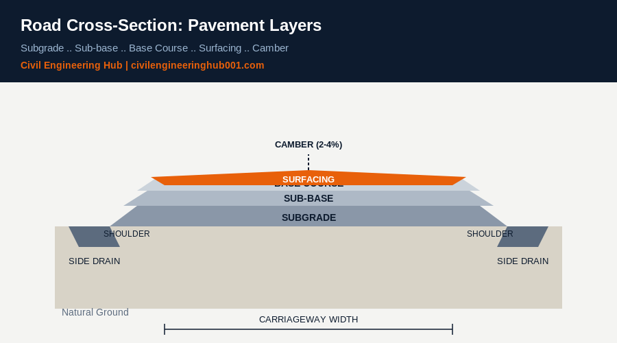
Every road you drive on started as a drawing before it became a surface under your tyres. A road cross-section drawing is the plan that shows how a road is built, layer by layer, from the subgrade all the way up to the wearing course.
If you cannot read this drawing correctly, you cannot supervise road works, verify quantities, or confirm that a contractor has built what the designer intended. Honestly, this is one of those drawings every civil engineer must master early, because it shows up on every road project regardless of size.
Quick Answer: A road cross-section drawing is a vertical cut across a road showing its width, camber, pavement layers (subgrade, sub-base, base, surfacing), side slopes, and drainage features. Reading it means understanding what each layer represents and how those dimensions translate into what actually happens on site.
What Exactly Is a Road Cross-Section Drawing
A cross-section is a cut taken at right angles to the direction of the road. Picture slicing through the road like a loaf of bread, then looking at that slice from the side. That slice shows you everything stacked inside the road structure.
In simple terms, a plan drawing tells you where the road goes. A cross-section tells you what the road is made of and how it sits on the ground. Both drawings work together, but the cross-section is the one that guides construction quality on site.
Cross-sections are typically drawn at regular intervals along the road, often every 20 to 50 metres depending on the terrain, and at any point where the ground changes significantly. Engineers use them to calculate earthwork volumes and to guide setting out on site.
The Layers You Will Find in Every Road Cross-Section
A pavement is not one solid slab. It is a system of layers, each one doing a specific job. The Kenya Road Design Manual Part III (Materials and Pavement Design) and equivalent standards such as AASHTO guide how these layers are sized and specified.
| Layer | Typical Function | Typical Thickness (Kenya Rural/Urban Roads) |
|---|---|---|
| Subgrade | Natural or improved ground that carries the entire pavement | Top 150-300mm compacted |
| Sub-base | Distributes load, provides drainage layer, protects subgrade | 150-300mm |
| Base course | Main structural layer carrying traffic loads | 150-250mm |
| Surfacing (wearing course) | Waterproofing and riding surface, resists wear | 25-50mm (surface dressing or asphalt) |
The truth is, these thicknesses are never arbitrary. They come from traffic loading calculations, CBR values of the subgrade, and the design life of the road. A site engineer reading a cross-section should always cross-check these figures against the pavement design report, not just the drawing alone.
Understanding Camber and Why It Is on Every Cross-Section
Camber is the slight slope given to the road surface from the centreline towards the edges. Its only job is to shed rainwater off the carriageway quickly, so water does not pond and weaken the pavement.
On a cross-section, camber is shown as a percentage or gradient, typically ranging from 2 percent to 4 percent for bituminous surfaces and slightly steeper for gravel roads because rougher surfaces need more slope to drain effectively.
| Road Surface Type | Typical Camber | Reason |
|---|---|---|
| Asphalt/bituminous | 2% – 2.5% | Smooth surface drains easily at lower slope |
| Surface dressed roads | 2.5% – 3% | Slightly rougher texture needs more fall |
| Gravel roads | 4% – 6% | Loose material needs steeper drainage slope |
If you are supervising road works and the camber on site does not match the cross-section, that road will pond water within the first rainy season. This is a detail junior engineers underestimate, yet it is one of the fastest ways a road fails early.
Reading the Side Slopes and Drainage Details
Beyond the carriageway, a cross-section also shows the shoulders, side drains, and embankment or cut slopes. Shoulders support the pavement edge and give room for vehicles to pull over. Side slopes are shown as a ratio, for example 1:2, meaning one unit vertical to two units horizontal.
Side drains carry water away from the road reserve. Their invert levels, widths, and shapes (trapezoidal or V-shaped) are all specified on the cross-section, and they must be built exactly as drawn. A drain that is shallower than designed will overflow onto the pavement during heavy rain, undermining the sub-base from below.
Cut and fill sections look different on a cross-section. In a cut section, the road sits below natural ground and the drawing shows the ground line above the road formation. In a fill section, the road sits above natural ground on an embankment, and the drawing shows fill material built up to the design level. Recognising which type of section you are looking at tells you immediately what earthworks activity should be happening on site.
Reading Dimension Callouts and Chainage on a Cross-Section
Every cross-section is tied to a chainage point along the road, usually written at the top or bottom of the drawing as something like CH 0+500, meaning 500 metres from the start point of the project. This chainage links the cross-section back to the plan and longitudinal section, so you always know exactly where on the ground that slice applies.
Dimension callouts on a cross-section run in a fixed order once you know what to look for. Horizontal dimensions describe carriageway width, shoulder width, and offsets to drains or the road reserve boundary. Vertical dimensions describe formation level, layer thicknesses, and depths of cut or fill. Levels are usually given as reduced levels (RL) tied to a benchmark, and these are the numbers you compare directly against what a level and staff reads on site.
In simple terms, treat every number on the drawing as either a horizontal measurement across the road or a vertical measurement up or down from a known level. Once you separate the two, the drawing stops looking crowded and starts making sense at a glance.
Road reserve width is also usually shown, and it matters beyond construction. It defines the legal boundary within which the road authority, whether KeNHA, KURA, or a county government, has control. Utility lines, fencing, and any future road widening are all planned within that reserve, so reading it correctly protects the project from encroachment disputes later.
How to Verify a Cross-Section Against What Is Built on Site
Reading the drawing is only half the job. Verifying it on site is where the real engineering happens. Here is a practical sequence site supervisors and engineers should follow.
| Step | What to Check | Tool/Method |
|---|---|---|
| 1 | Formation level at centreline and edges | Level and staff, checked against design levels |
| 2 | Layer thickness after compaction | Trial pits or DCP test |
| 3 | Camber gradient across the carriageway | Straight edge and level, or camber board |
| 4 | Side slope angle | Slope template or clinometer |
| 5 | Drain invert level and gradient | Level and staff along the drain line |
This is where classroom theory meets real site practice. You can understand a cross-section perfectly on paper, but if you never physically check formation levels with a level and staff, you will not catch the errors that cost money and cause premature road failure.
Common Mistakes Engineers Make Reading Cross-Sections on Site
The most frequent mistake is confusing the plan view with the cross-section and applying the wrong dimension to the wrong direction. A width shown on a cross-section is measured across the road, not along it.
Another common error is ignoring the difference between “compacted thickness” and “loose thickness” of a layer. Materials compact down once rolled, so the loose spread thickness on site must always be more than the final compacted thickness shown on the drawing. This detail catches out many new site engineers and clerks of works.
Finally, some site teams treat the cross-section as a rough guide rather than a binding document. Honestly, that mindset causes more road failures in Kenya than any material defect. The cross-section is a contractual and technical document, and it must be followed to the exact dimension unless a formal variation is approved.
Frequently Asked Questions
Q: What is the difference between a road cross-section and a longitudinal section?
A cross-section is a cut perpendicular to the road direction showing width, layers, and camber. A longitudinal section runs along the length of the road showing gradient changes, vertical curves, and chainage. Both are needed together for full construction guidance. Engineers read the longitudinal section for levels along the road and the cross-section for what happens at each of those points.
Q: Why do road cross-sections show different layers than building foundation drawings?
Roads carry moving, repeated traffic loads across their full length, so they need layered pavement systems designed for fatigue and drainage. Buildings carry static point and line loads through foundations into isolated or strip footings. The engineering principle of spreading load is shared, but the load type and drawing purpose are different, which is why the two drawings look nothing alike.
Q: How often should cross-sections be drawn along a road project?
Standard practice under most road design manuals, including the Kenya Road Design Manual, is every 20 to 50 metres on straight sections, with additional sections at any point of significant ground change, culvert location, or junction. Shorter intervals give more accurate earthwork volume calculations, especially in undulating terrain.
The Takeaway
A road cross-section is not just a technical drawing to file away. It is the single reference point that tells you what a road should be made of, how it should drain, and how it should sit on the ground it is built on.
Master this drawing and you will supervise road works with confidence, catch defects before they become failures, and speak the same language as the designers who produced the drawing. That is the difference between a technician who follows instructions and an engineer who understands them.
Want more practical construction knowledge delivered directly to you?
Subscribe to our YouTube channel: https://www.youtube.com/@TheCivilEngineeringHub-001
PS: Join our engineering WhatsApp community for daily learning at +254731393520