

Every rainy season, the same culverts fail. Water backs up, the road embankment saturates, and within a few storms the carriageway starts to slump. Most of the time the cause is not bad concrete or poor workmanship. It is a culvert that was never sized correctly in the first place.
This guide walks you through how to size a culvert for road drainage using the rational method, how to pick the right diameter and shape, and the site mistakes that quietly turn a correctly designed culvert into a recurring maintenance problem.
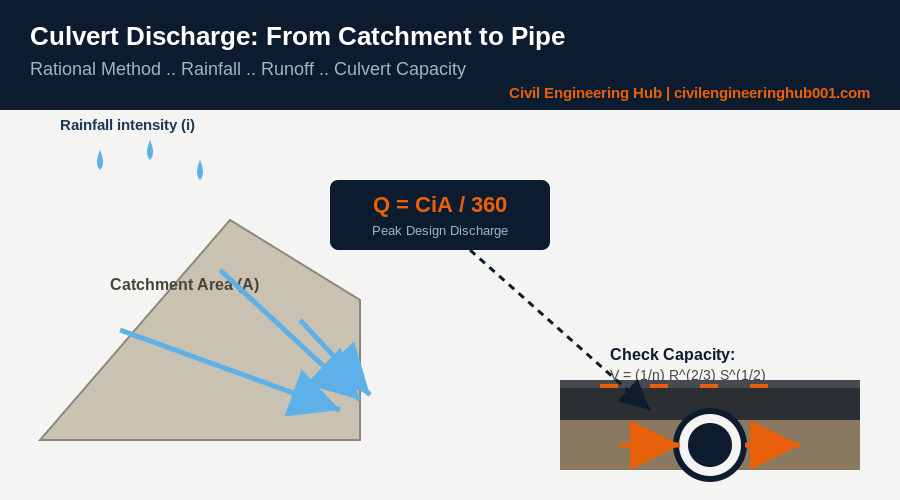
Quick Answer: Culvert size is determined by calculating the peak design discharge from the catchment (commonly using the Rational Method, Q = CiA/360), then selecting a culvert diameter or box size whose hydraulic capacity, checked using Manning’s equation, safely carries that flow with adequate freeboard.
What a Culvert Is Actually Doing on Your Road
A culvert is not just a pipe under a road. It is a structure that has to move a specific volume of water, from a specific catchment, within a specific time, without drowning the road or scouring the outlet.
On site, engineers often inherit a culvert size from a standard drawing without checking whether it matches the actual catchment feeding it. That is where the trouble starts. A 600mm pipe that worked fine on a small farm access road will not cope with a catchment three times larger just because the terrain looks similar.
The truth is, culvert sizing is a hydrology problem before it is a structural one. Get the water quantity wrong, and no amount of good concrete work will save the crossing.
Calculating Design Discharge Using the Rational Method
For catchments under roughly 50 hectares, which covers most rural and estate road crossings, the Rational Method remains the standard approach referenced in the Kenya Road Design Manual Part III (Drainage Design).
The formula is:
Q = CiA / 360
Where:
- Q = peak discharge (cubic metres per second)
- C = runoff coefficient (depends on land cover and soil type)
- i = rainfall intensity (mm/hour) for the design storm
- A = catchment area (hectares)
In simple terms, you are estimating how much rain falls on the catchment, how much of it actually runs off instead of soaking in, and how fast it arrives at your crossing point.
Typical runoff coefficients used on Kenyan road projects:
| Catchment Surface | Runoff Coefficient (C) |
|---|---|
| Steep bare ground, rock | 0.60 – 0.80 |
| Cultivated farmland, moderate slope | 0.30 – 0.50 |
| Grassland, gentle slope | 0.15 – 0.30 |
| Forest, flat terrain | 0.10 – 0.20 |
Design storm return periods also matter. Minor culverts on low-volume roads are typically designed for a 10-year storm. Major crossings on trunk roads are designed for 25 to 50-year storms, in line with the design manual’s risk categories.
Selecting the Culvert Size Once You Have the Discharge
Once you have Q, you check whether a given culvert size can actually carry it. This is where Manning’s equation comes in, used to estimate the pipe’s hydraulic capacity under the expected flow conditions:
V = (1/n) R^(2/3) S^(1/2)
Where V is flow velocity, n is the roughness coefficient of the pipe material, R is the hydraulic radius, and S is the culvert’s longitudinal slope.
On most site projects, engineers use standard culvert capacity charts rather than solving Manning’s equation by hand every time. As a practical starting reference:
- 600mm diameter pipe: suitable for catchments up to about 5 hectares under moderate slope conditions.
- 900mm diameter pipe: suitable for catchments up to about 15 hectares.
- 1200mm diameter pipe or twin 900mm cells: catchments up to about 30 hectares.
- Box culverts: required beyond this range, or wherever headroom is restricted and a wide, shallow waterway is needed.
Always add freeboard. In simple terms, do not size a culvert to run completely full at design flow. Kenya Road Design Manual guidance recommends the culvert soffit sit above the design water level, so the structure has margin during storms that exceed the design assumption.
Common Site Mistakes That Cause Culverts to Fail
Honestly, most culvert failures trace back to a handful of repeat mistakes, not exotic engineering problems.
Undersized catchment estimation is the biggest one. Site teams often measure the catchment from a rough site walk instead of a proper topographic delineation, and end up underestimating the contributing area.
Wrong or missing inlet and outlet protection is the second. A culvert can be sized correctly and still fail if the inlet scours and collapses, or the outlet erodes the embankment because there is no apron or rip-rap to dissipate energy.
Flat or reversed gradient is the third. If the culvert invert is laid flatter than the design slope, or worse, sloped the wrong way during construction, sediment builds up and the effective capacity drops well below what was designed.
Blockage from debris and siltation rounds out the list. A culvert without a working headwall and trash screen will silt up within a season or two, regardless of how well it was sized on paper.
Frequently Asked Questions
Q: What is the minimum culvert size recommended for road crossings?
Most road design manuals, including Kenya’s, set 600mm as the minimum diameter for road culverts, even where calculated discharge is smaller. This minimum size allows for maintenance access and reduces the risk of complete blockage from debris.
Q: How often should culvert sizing be reviewed on an existing road?
Review culvert sizing whenever the upstream catchment changes significantly, for example through new development, deforestation, or a change in farming practice. A culvert designed for a bush catchment ten years ago may be undersized today.
Q: Can I use a smaller culvert if I add more than one pipe?
Yes, multiple smaller culverts, referred to as multi-cell or twin culverts, can replace one large pipe and are common where headroom is limited. The combined hydraulic capacity must still meet the calculated design discharge, and each cell needs its own inlet protection.
Conclusion
Culvert sizing is a calculation, not a guess copied from the last project. Work out your catchment area properly, apply the Rational Method to get design discharge, check capacity against a recognised culvert chart, and protect the inlet and outlet on site. Do that consistently, and your crossings will survive the storms that take out the ones built on assumptions.
Want more practical construction knowledge delivered directly to you?
Subscribe to our YouTube channel: https://www.youtube.com/@TheCivilEngineeringHub-001
PS: Join our engineering WhatsApp community for daily learning at +254731393520