
Most site delays don’t start with bad workmanship. They start with someone misreading a drawing. A mason builds a wall 200mm off. A contractor orders the wrong window size. A supervisor approves work that does not match the architect’s intent, and by the time anyone notices, it is already cast in concrete.
If you work in construction in any capacity, whether you are a civil engineer, structural engineer, quantity surveyor, electrician, plumber, or site supervisor, you need to read architectural drawings with confidence. This guide breaks down exactly how to do that, using the symbols, scales, and cross-checks that matter on a real Kenyan site.
Quick Answer: Reading architectural drawings on site means understanding the drawing set (plans, elevations, sections, details), knowing standard symbols and abbreviations, checking the scale and dimension strings correctly, and cross-referencing against structural and MEP drawings before any work is approved.
What Makes Up a Complete Architectural Drawing Set?
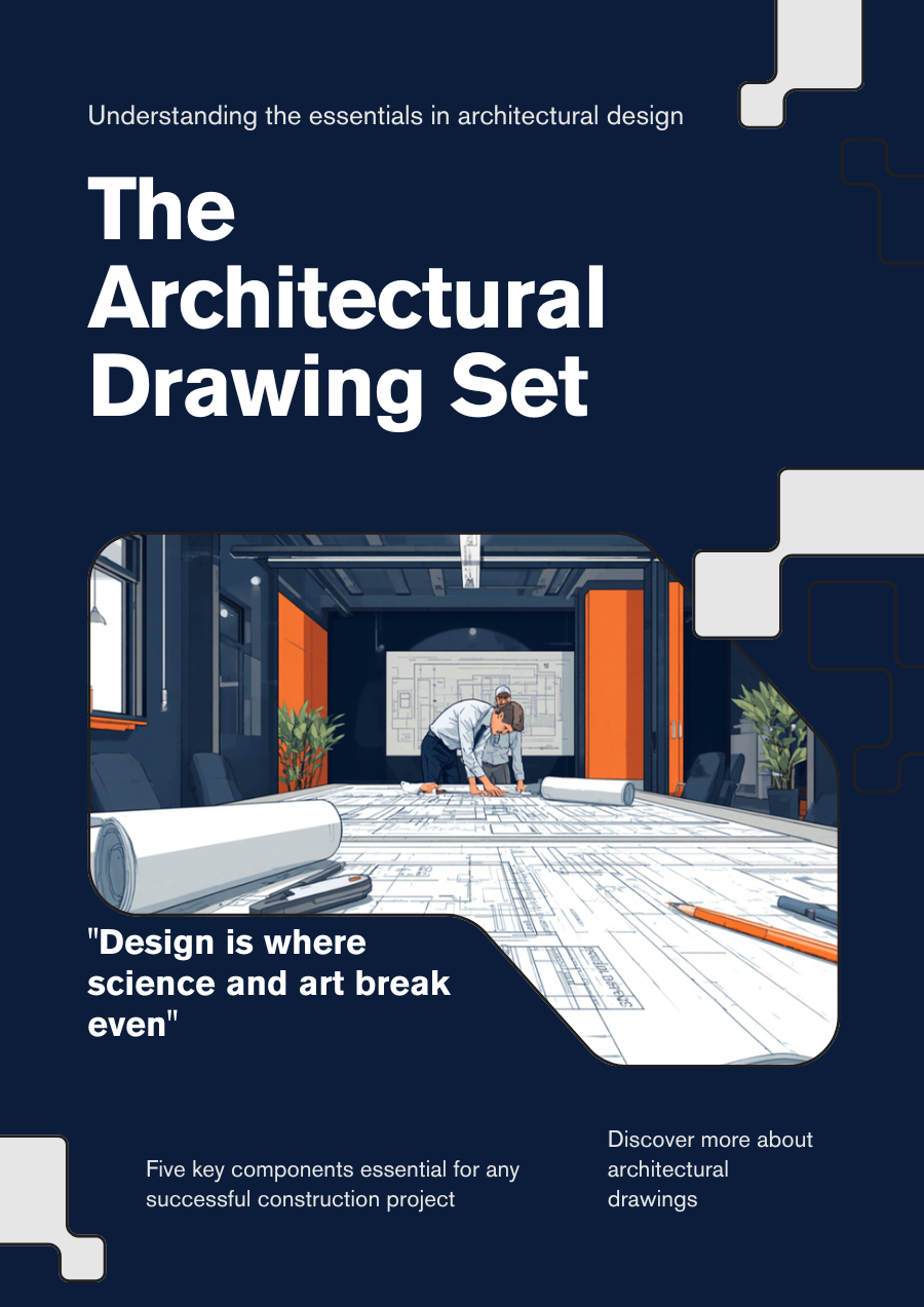
An architectural drawing set is never just one sheet. It is a coordinated package, and missing even one part of it is how mistakes slip through.
A standard set includes: the site plan (shows the building’s position on the plot), floor plans (each level, showing walls, doors, rooms, and dimensions), elevations (external views from each side), sections (vertical cuts through the building showing floor-to-floor heights), and detail drawings (close-up views of tricky junctions like staircases, parapets, or window reveals).
The truth is, most site disputes happen because someone worked from a floor plan alone without checking the section or the details. A floor plan tells you where a wall goes. A section tells you how tall it is and what sits above it. You need both before you build anything.
Common Architectural Symbols and Abbreviations You Must Know
Architects use a standard symbol language so drawings stay clean and readable. If you cannot read these, you are guessing.
| Symbol / Abbreviation | Meaning |
|---|---|
| DPC | Damp Proof Course |
| FFL | Finished Floor Level |
| RWDP | Rain Water Down Pipe |
| W1, W2, D1, D2 | Window and door reference tags, cross-checked against the schedule |
| Hatched wall | Existing wall to remain |
| Dashed line | Hidden element, usually above or below the cut plane |
| N Arrow | North orientation, critical for sun path and drainage falls |
In simple terms, every symbol on the drawing is shorthand for a decision the architect already made. Your job is to decode it correctly, not assume it.
How Scale and Dimensions Work on Architectural Drawings
Architectural drawings in Kenya are typically produced at 1:100 or 1:50 for floor plans, and 1:20 or 1:5 for construction details. Never measure a drawing with a ruler and multiply by the scale, because printed copies shrink and stretch during photocopying or PDF export. Always use the written dimension strings on the drawing.
Here is why this matters on site: dimensions are usually given in millimetres, running from a grid line or a wall face. Confirm whether a dimension is to the structural face, the finished face, or the centreline of a wall. This single detail decides whether your room comes out 20mm short or exactly to spec.
Under the Kenya Building Code 2024, setbacks and room dimensions referenced on approved drawings must match what is submitted to the county for approval. That means any dimension change on site, even a small one, should be confirmed against the approved set before you proceed.
How to Cross-Check Architectural Drawings Against Structural and MEP Drawings
An architectural drawing shows design intent. It does not show you where the beams, columns, or conduit runs actually go. That is why cross-checking against the structural and MEP drawings is non-negotiable before work starts.
Follow this sequence before executing any wall, opening, or chase:
- Confirm the wall or opening position on the architectural floor plan.
- Check the structural drawing for any beam, column, or slab edge in that same location.
- Check the MEP drawing for conduit, pipe, or duct runs that might clash.
- Flag any conflict with an RFI before you cut, chase, or cast.
Honestly, this step is where the different professions on a project actually need each other. An electrician who chases a wall without checking the structural drawing can cut through reinforcement. A mason who builds a partition without checking the MEP layout blocks a pipe run that now needs to be broken out later.
Common Mistakes When Interpreting Architectural Drawings on Site
A few errors show up again and again on Kenyan sites, and all of them are preventable.
Working from an outdated revision is the most common one. Drawings get revised, and the revision cloud with a triangle number tells you exactly what changed. Always check the revision number in the title block before you build from any sheet.
Ignoring the door and window schedule is another. The plan shows a tag like D1, but the actual size, material, and swing direction live in the schedule on a separate sheet. Building from the tag alone without checking the schedule leads to wrong openings.
Finally, confusing a similar-looking dimension line for a grid line causes real damage. Grid lines are reference axes used across all drawing types. Dimension lines are specific measurements. Mixing them up misplaces entire structural elements.
Frequently Asked Questions
Q: What is the difference between an architectural drawing and a structural drawing?
An architectural drawing shows the design intent, room layout, finishes, and aesthetics of a building. A structural drawing shows the engineering behind it, including beam sizes, column positions, reinforcement, and load paths. Both must be read together, never in isolation.
Q: Why do architectural drawings use different scales for plans and details?
Plans use smaller scales like 1:100 because they cover a large area. Details use larger scales like 1:5 or 1:10 because they need to show precise junctions, such as how a window meets a wall. Reading the correct scale for each sheet type avoids measurement errors.
Q: Who is responsible for resolving a conflict between architectural and structural drawings?
The lead consultant, usually the architect or the project engineer, resolves conflicts through an RFI process. Site teams should never resolve a drawing conflict on their own judgment. Always raise it formally and wait for written clarification before proceeding.
Conclusion
Reading architectural drawings well is not a talent some people have and others do not. It is a skill built through repetition, knowing your symbols, respecting the scale, and always cross-checking against structural and MEP sheets before you commit to work on site. Master this, and you cut errors, rework, and disputes before they start.
—
Want more practical construction knowledge delivered directly to you?
Subscribe to our YouTube channel: https://www.youtube.com/@TheCivilEngineeringHub-001
PS: Join our engineering WhatsApp community for daily learning at +254731393520