

Most structural engineering students can calculate the required steel area for a beam. Fewer can actually detail it the way a fabricator or steel bender on site needs to see it. That gap is exactly why a good mentor tells you to master detailing before you move into full structural design.
In simple terms, reinforcement detailing is the process of turning your calculated steel area into a drawing a steel fixer can follow without asking you a single question. It covers bar sizes, spacing, laps, curtailment, and stirrup arrangement.
This guide walks you through detailing a reinforced concrete beam from the structural drawing to the finished bar bending schedule, the same way you would approach it on a real site.
Quick Answer: Reinforcement detailing for a concrete beam means converting the calculated tension, compression, and shear steel into a bar bending schedule and placement drawing that specifies bar diameter, spacing, laps, curtailment points, and stirrup arrangement, following code requirements such as BS 8110 or Eurocode 2.
What Reinforcement Detailing Actually Means for a Beam
Design gives you the numbers: area of steel required, moment capacity, shear force. Detailing turns those numbers into bars a steel fixer can bend, cut, and place on site.
The truth is, a beam can be perfectly designed and still fail on site if the detailing is wrong. Wrong lap lengths, missed stirrup spacing near supports, or poor bar curtailment cause real structural problems, not just paperwork issues.
Good detailing answers four questions for every beam: how many bars, what diameter, where they start and end, and how the stirrups are spaced along the span.
Step 1: Start With the Structural Drawing, Not the Bar Bending Schedule
Before you draw a single bar, read the structural drawing fully. Confirm the beam size (width by depth), span, support conditions, and any reinforcement notes already shown on the drawing.
Check whether the beam is simply supported, continuous, or cantilevered, because the bar arrangement changes completely between these three.
For simply supported beams, main tension steel goes at the bottom at midspan. For continuous beams, top steel over the supports carries hogging moment while bottom steel carries sagging moment at midspan. Cantilever beams reverse this, with tension steel at the top.
This is also the point where you confirm the concrete cover required. Cover protects reinforcement from corrosion and gives the required fire rating, and it changes depending on exposure condition. A beam exposed to weather needs more cover than one enclosed inside a building, so do not copy cover values from one project to the next without checking the exposure class first.
Step 2: Set the Main Reinforcement (Tension and Compression Bars)
Main bars resist bending. Start with the steel area from design calculations, then select a bar diameter and number of bars that satisfy that area with practical spacing on site.
| Bar Diameter (mm) | Area per Bar (mm2) | Bars Needed for As = 1200 mm2 |
|---|---|---|
| 12 | 113 | 11 |
| 16 | 201 | 6 |
| 20 | 314 | 4 |
| 25 | 491 | 3 |
Keep minimum clear spacing per BS 8110: not less than the bar diameter, the maximum aggregate size plus 5mm, or 20mm, whichever is greatest. The Kenya Building Code follows a similar minimum spacing principle.
Step 3: Detail Shear Links (Stirrups) Correctly
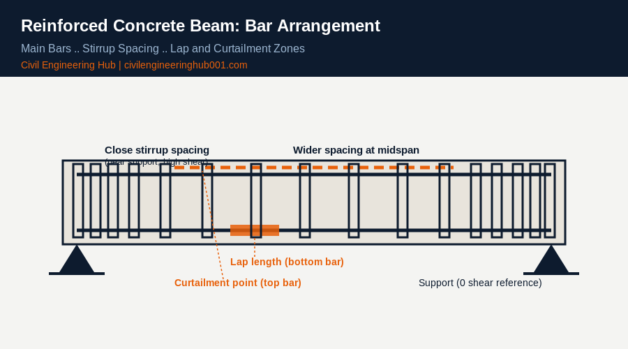
Shear force is highest near the supports and drops toward midspan. That is why stirrup spacing tightens near supports and can open up toward the centre of the beam.
- Calculate shear force distribution along the full span.
- Provide closer stirrup spacing within a distance of twice the effective depth from each support.
- Increase spacing gradually toward midspan, generally capped at 0.75d for vertical stirrups under both BS 8110 and Eurocode 2 guidance.
- Never exceed the maximum spacing given in your design code, regardless of what the computed shear alone suggests.
Step 4: Handle Anchorage, Laps, and Bar Curtailment
Bars do not run the full length of a beam without reason. Curtailment is where you reduce the number of bars once the bending moment has dropped enough that fewer bars can carry it safely.
Lap lengths must follow the code multiplier, typically 40 to 50 times the bar diameter for tension laps under BS 8110, and should never fall in the highest stress zone of the beam.
Honestly, this is where most students lose marks and most site issues start. If you curtail a bar too early or lap two bars in the wrong zone, you have created a weak point in the beam that no amount of good concrete will fix.
Anchorage matters just as much at the ends of a simply supported beam. Bars must extend far enough into the support to develop full bond strength, otherwise the steel can slip before it reaches its design capacity. Always check the development length against the code, not against what “looks enough” on the drawing.
Step 5: Cross-Check Your Detailing Against the Bar Bending Schedule
Once the drawing is complete, produce the bar bending schedule (BBS). This lists every bar mark, diameter, shape, cutting length, and quantity needed for the beam.
A good BBS does two things at once. It gives the steel fixer an exact list to bend and cut from, and it gives you, the engineer, a final chance to catch a mistake before concrete is poured. Cross-check every bar mark on the schedule against the drawing before you issue it for construction.
Frequently Asked Questions
Q: What is the difference between structural design and structural detailing?
Design calculates the steel area and moment capacity a beam needs. Detailing turns those numbers into a buildable drawing that specifies bar size, spacing, laps, and curtailment. You need both, but detailing is where the theory becomes something a steel fixer can actually build.
Q: Which code should I follow for beam detailing in Kenya?
Most practising engineers in Kenya reference BS 8110 for detailing rules, alongside the Kenya Building Code for general construction requirements. Newer designs are increasingly moving toward Eurocode 2, so confirm what your firm or county approval authority requires before finalizing a drawing.
Q: Why do stirrups get closer together near the supports?
Because shear force is highest near the supports and decreases toward midspan. Closer stirrup spacing at the supports controls diagonal cracking where shear stress is greatest, protecting the beam from a shear failure.
Conclusion
Reinforcement detailing is the bridge between structural theory and a beam that actually stands. Master the sequence: read the drawing, set your main bars, detail your stirrups, then handle laps and curtailment with the correct code in hand.
That is exactly why detailing comes before full structural design in a proper learning path. Once you can detail a beam correctly, the design calculations behind it will make far more sense.
Want more practical construction knowledge delivered directly to you?
Subscribe to our YouTube channel: https://www.youtube.com/@TheCivilEngineeringHub-001
PS: Join our engineering WhatsApp community for daily learning at +254731393520