

Every building has one job.. take the weight of everything inside and on top of it, and deliver that weight safely to the ground. The route that weight follows is called the load path, and if that route is broken anywhere, the building has a problem, even if every individual member looks fine on paper.
The truth is, most structural failures on site are not caused by a weak beam or a bad mix. They happen because someone interrupted the load path.. a column was shifted, a beam was cut for a pipe, or a wall was built where the drawings showed nothing underneath it.
In simple terms, a load path is the chain of members that carries a load from where it lands to the soil. In this guide we walk through how loads enter a frame, how they travel, a worked example with real numbers, and the site mistakes that break the chain. It applies to engineers, architects, QSs, masons, plumbers, electricians and site supervisors alike.
Quick Answer: A load path is the continuous route a load follows through a building frame, from the slab to the beams, then columns, then foundations, and finally into the ground. Every member in that chain must be strong enough and properly connected, or the building cannot carry its loads safely.
What is a load path and why does it decide whether a building stands?
A load path is simply the sequence of structural members that a force passes through. In a typical reinforced concrete frame the sequence is slab, beam, column, foundation, soil. Each member receives load from the one above it and hands it down to the one below.
Think of a bucket chain at a fire. If one person drops out, the water stops moving, and everyone upstream is now carrying a load they were never meant to hold. Structures behave the same way.. when one member is removed or weakened, the load finds another route, usually through a member that was not designed for it.
Honestly, this is the first thing a site team should understand before touching any structural element. Designers check the load path under BS 8110 or Eurocode 2 (EN 1992-1-1), and the Kenya Building Code expects the structure to be designed so that loads reach the ground without overstressing any element. Your job on site is to build what the path requires, not what is convenient.
How do loads enter a building frame?
Before we follow a load down, we need to know what is being carried. Structural engineers group loads into three families: permanent loads, variable loads and environmental loads.
Permanent loads, also called dead loads, are the weight of the structure itself plus fixed items like screed, tiles, plaster and fixed partitions. Variable loads, also called imposed or live loads, come from people, furniture and stored goods. Environmental loads include wind and, in some regions, seismic action.
| Load type | Examples | Typical value | Reference |
|---|---|---|---|
| Dead (self weight) | Reinforced concrete | About 25 kN/m3 | BS 648 / EN 1991-1-1 |
| Dead (finishes) | Cement screed with tiles | About 1.0 to 1.5 kN/m2 | EN 1991-1-1 |
| Imposed (residential) | Bedrooms, living areas | About 1.5 kN/m2 | BS 6399-1 / EN 1991-1-1 |
| Imposed (office) | Offices, classrooms | About 2.5 to 3.0 kN/m2 | BS 6399-1 / EN 1991-1-1 |
| Wind | Pressure on walls and roof | Depends on site and height | EN 1991-1-4 |
Vertical loads follow the path from slab to ground. Lateral loads such as wind follow a different route.. they hit the cladding and walls, travel into the floor slabs, which act like stiff plates called diaphragms, and are then carried by shear walls, lift cores or braced frames down to the foundation.
That second path is the one people forget. A building can carry its own weight beautifully and still fail sideways if the lateral path is not complete.
How does load travel from the slab to the foundation?
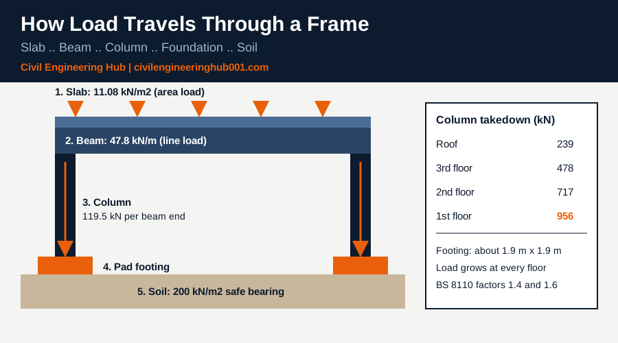
Let us follow one kilonewton from the top of the slab to the soil. At every step the load changes form, from an area load on the slab, to a line load on the beam, to a point load on the column, and finally to a pressure on the soil.
| Step | Member | What it receives | What it passes on | Key site concern |
|---|---|---|---|---|
| 1 | Slab | Self weight, finishes, people | Line load to supporting beams | Cover, bar spacing, thickness |
| 2 | Beam | Slab reaction and wall load | Point loads to columns | Links, anchorage, no cutting |
| 3 | Column | Beam reactions from every floor | Axial load to the footing | Alignment, vibration, honeycombing |
| 4 | Foundation | Column load | Pressure to the soil | Founding depth, bearing capacity |
| 5 | Soil | Foundation pressure | Resists through bearing | Soil type, water table |
Notice that every step depends on the one below it. The slab trusts the beam, the beam trusts the column, and the column trusts the footing. Nobody on the chain can be skipped.
What does a load path calculation look like with real numbers?
Here is a simple takedown for a four storey frame using BS 8110 partial factors of 1.4 for dead load and 1.6 for imposed load. Assume a 150 mm slab spanning one way between beams spaced 4 m apart, with beams spanning 5 m between columns.
Step 1.. slab load. Self weight is 0.15 m x 25 = 3.75 kN/m2. Add screed and tiles at 1.2, plaster at 0.25 and a partition allowance of 1.0, giving a characteristic dead load of 6.2 kN/m2. Imposed load for residential use is 1.5 kN/m2. The design load is 1.4(6.2) + 1.6(1.5) = 11.08 kN/m2.
Step 2.. beam load. The beam collects a 4 m strip of slab, so 11.08 x 4 = 44.3 kN/m. Add the factored beam rib self weight of about 3.5 kN/m to get roughly 47.8 kN/m. Over a 5 m span, each end reaction is 47.8 x 5 / 2 = about 119.5 kN.
Step 3.. column load. An internal column receives a beam from each side, so 2 x 119.5 = about 239 kN per floor. Real continuous beams push the interior reaction up by roughly 10 percent, which the designer accounts for, but the simple figure shows the pattern.
| Level | Load added (kN) | Cumulative column load (kN) |
|---|---|---|
| Roof | 239 | 239 |
| Third floor | 239 | 478 |
| Second floor | 239 | 717 |
| First floor | 239 | 956 |
Step 4.. footing size. Divide the factored load by about 1.45 to get a service load near 660 kN. On soil with a safe bearing capacity of 200 kN/m2, the required area is 660 / 200 = 3.3 m2, which means a pad of roughly 1.9 m by 1.9 m.
This is why the ground floor column is always bigger than the roof column, and why a footing that looks oversized on the drawing is usually correct. It is carrying every floor above it.
What breaks the load path on a real construction site?
Drawings give the designer’s intent. Site decisions can undo it in a single afternoon. These are the most common ways the chain gets broken in Kenya.
- Cutting beams and columns for services. A plumber or electrician chops a beam to pass a pipe, removing concrete and sometimes reinforcement. Always agree sleeve positions with the engineer before the pour.
- Shifting a column between floors. If an upper column does not sit directly over the one below, the beam beneath becomes a transfer beam it was never designed to be.
- Building walls where the drawings show none. A masonry wall on a slab with no beam under it adds a heavy line load the slab was not sized for. Check wall positions against the structural plan.
- Poor concrete at joints. Honeycombing at the beam and column junction weakens exactly the spot where the load changes direction. Vibrate properly and check the formwork is tight.
- Removing props too early. A slab that has not gained enough strength is still resting on its props, so striking early forces it to carry load before it is ready. Follow the striking times in the specification.
The Kenya Building Code and NCA requirements put responsibility on registered professionals for structural work, which means a site decision that alters the structure needs the engineer’s written approval, not a verbal go-ahead.
Frequently Asked Questions
Q: What is the difference between a load path and a load takedown?
A load path is the route a load follows through the structure. A load takedown is the calculation that adds up the load at each level along that route. The path tells you where the load goes, and the takedown tells you how much of it arrives at each member.
Q: Can I remove a wall without affecting the load path?
Only if the wall is not structural, and you cannot know that by looking at it. Even a block wall can carry a slab edge or support a beam above. Ask the structural engineer to confirm from the drawings before any demolition, and prop the structure first if there is any doubt.
Q: Why do columns get smaller toward the roof?
Because each floor adds load as you go down. The roof column only carries the roof, while the ground floor column carries every storey above it. Many Kenyan buildings keep the same column size for simplicity and reduce the reinforcement instead.
Conclusion
A building is only as strong as its weakest link in the load path. Every slab, beam, column and footing has to be built as designed, connected properly, and left intact by every trade that follows.
Before you cut, shift, or remove anything, ask one question.. where does this load go if this member is gone? If you cannot answer it, stop and consult the engineer. That one habit separates a careful professional from a risky one.
Want more practical construction knowledge delivered directly to you?
Subscribe to our YouTube channel: https://www.youtube.com/@TheCivilEngineeringHub-001
PS: Join our engineering WhatsApp community for daily learning at +254731393520