

A structural engineer can design the perfect beam on paper and still watch it fail on site if the detailing is wrong. Beam detailing is where design theory meets buildable reality, and it is the single skill that separates an engineer who can calculate from one who can actually get a building built correctly.
Quick Answer: Beam detailing is the process of translating structural design calculations into a buildable drawing that shows exact bar sizes, spacing, laps, anchorage lengths and curtailment points for a reinforced concrete beam, following a recognized code such as BS 8110 or Eurocode 2.
Honestly, most engineering graduates can run a beam design calculation. Far fewer can produce a detail that a steel fixer on site can read without confusion. That gap is exactly why mentors in this industry, including mine, insist that anyone serious about structural engineering starts with detailing before moving into full design. You cannot design safely what you do not know how to build.
What Is Beam Detailing and Why It Matters
Beam detailing is the drawing and specification stage that follows structural analysis and design. Once the engineer has calculated the required reinforcement area, the detail drawing shows how that steel is actually arranged inside the beam, main bars, stirrups, laps, hooks and curtailment points included.
In simple terms, design tells you how much steel you need. Detailing tells you exactly where that steel goes, how it is held in place, and how it connects to the rest of the structure. A beam that is correctly designed but poorly detailed can still fail through inadequate anchorage, wrong lap lengths, or congested reinforcement that concrete cannot properly surround.
On Kenyan sites, this is where a lot of avoidable failures happen. The design office gets the numbers right, but the bar bending schedule or the site sketch loses critical information, and the steel fixer ends up guessing.
Reading a Beam Detail Drawing — The Key Elements
A complete beam detail drawing communicates far more than a design calculation sheet. Every experienced site engineer looks for the same set of elements before allowing concrete to be poured.
| Element | What It Shows | Why It Matters On Site |
|---|---|---|
| Main reinforcement (bottom and top bars) | Bar diameter, number of bars, and their position along the span | Resists bending moment at midspan and supports |
| Stirrups / links | Diameter and spacing, often closer near supports | Resists shear force and holds main bars in position |
| Curtailment points | Where bars can be safely cut short along the span | Saves steel while maintaining strength where it is needed |
| Lap lengths | Length of overlap where two bars are joined | Ensures continuity of tension force between bars |
| Anchorage / bend lengths | How far a bar extends into a support | Prevents the bar from pulling out under load |
| Cover | Concrete thickness between the bar and the surface | Protects steel from corrosion and provides fire resistance |
If any one of these is missing from a drawing handed to site, the fixer will improvise. That means real risk to the building’s performance, not just an aesthetic problem.
Main Reinforcement, Stirrups and Anchorage Explained
The truth is, beam detailing follows a logical pattern once you understand the bending moment and shear force diagrams behind it. A simply supported beam carries maximum sagging moment at midspan, so the bottom bars, which resist tension there, run the full length with adequate anchorage into the supports.
Near the supports of a continuous beam, the top of the beam goes into tension instead, which is why top bars are detailed to extend past the support and into the adjoining span. Getting this reversal wrong is one of the most common detailing errors young engineers make when they move from single-span to continuous beam design.
Stirrup spacing follows the shear force diagram closely. Shear is highest near the supports, so stirrups are spaced closer together there and can open up toward midspan where shear reduces. A typical detail might specify Y8 stirrups at 150mm centers near supports, opening to 250mm centers at midspan, though the exact spacing always comes from the shear design calculation, not a rule of thumb.
Anchorage length is not negotiable. A bar that is not embedded far enough into a support has no way to transfer its tension force into the structure, no matter how correctly the beam was designed on paper.
BS 8110 vs Eurocode 2 — What Changes in Detailing Requirements
Most structural offices in Kenya were trained on BS 8110, and it remains widely used for reinforced concrete detailing, though Eurocode 2 (EC2) is increasingly referenced, especially on projects with international consultants or funding.
| Requirement | BS 8110 | Eurocode 2 (EC2) |
|---|---|---|
| Minimum tension reinforcement | Based on 0.13% to 0.24% of section depending on steel grade | Formula-based, tied to concrete tensile strength (fctm) |
| Anchorage/bond stress approach | Simplified bond stress tables | Design bond strength calculated from concrete strength class |
| Lap length calculation | Based on bar size and bond stress category | More detailed, factors in bar position and transverse reinforcement |
| Deflection control | Span/depth ratio tables | Similar approach, with adjusted basic ratios |
For students and young engineers in Kenya, the practical move is to master BS 8110 detailing thoroughly first, since it still governs the majority of local practice under the Kenya Building Code framework, then layer Eurocode 2 principles on top once the fundamentals are solid. Trying to learn both codes simultaneously without a strong BS 8110 base tends to confuse rather than accelerate learning.
Common Beam Detailing Mistakes on Site
In simple terms, most detailing failures are not calculation errors. They are communication errors between the design drawing and the site.
- Insufficient lap length at construction joints, often shortened informally by the fixer to save steel
- Wrong curtailment where bars are cut too early, leaving the beam under-reinforced at a critical section
- Congested reinforcement at beam-column junctions where bars physically cannot fit, forcing site improvisation
- Missing top steel over continuous supports, a mistake that shows up as cracking months after handover
- Inadequate cover, usually from poorly placed or missing spacer blocks
Every one of these is preventable with a clear, fully dimensioned detail drawing and a site team that has been walked through it, not just handed a stack of paper.
How Beam Detailing Connects to the Bar Bending Schedule
Every beam detail drawing eventually becomes a bar bending schedule, the document the steel fixer and the site storekeeper actually work from day to day. In simple terms, the detail drawing is the engineer’s language and the bar bending schedule is the translation into a language the fabrication yard understands: bar mark, diameter, shape code, cutting length and quantity.
This is where small detailing errors compound into big procurement problems. If a curtailment point is unclear on the drawing, the bar bending schedule will carry that error into the cutting length calculation, and the fabrication yard will cut steel that is either too short to achieve proper anchorage or wastefully long. On a busy Kenyan site running multiple pours a week, that mistake is rarely caught until the concrete gang is already standing at the beam waiting for steel that does not fit.
A disciplined structural engineer checks the bar bending schedule against the detail drawing before it goes to procurement, not after the steel arrives on site. That single habit, more than any software skill, is what separates engineers whose sites run smoothly from those who spend their days fixing avoidable rework.
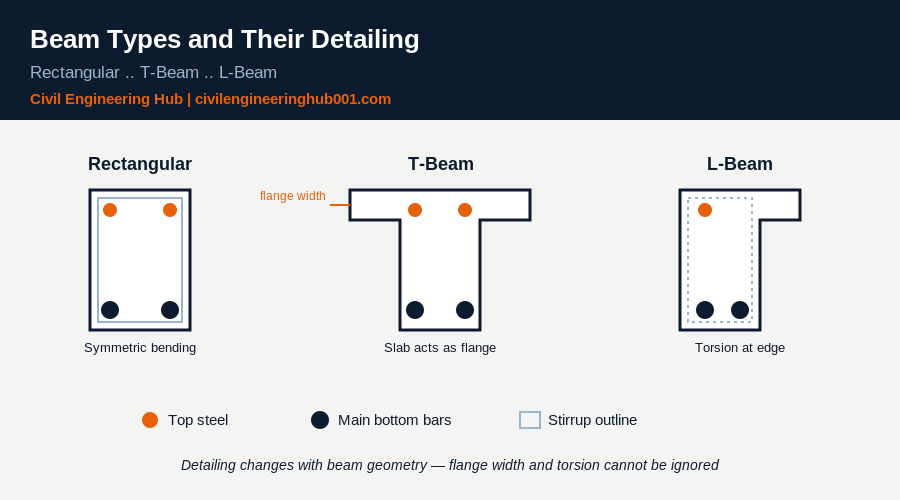
Detailing Differences Between Rectangular, T-Beams and L-Beams
Not every beam is detailed the same way, and this is a point many students miss until they hit it on a real drawing set. A rectangular beam, common in simple residential framing, has a straightforward detail with main bars top and bottom and stirrups enclosing both.
A T-beam, formed where a beam casts monolithically with a slab, behaves differently in bending because the slab acts as a compression flange. That changes how much bottom steel is actually required at midspan, since the wider compression area shares the load differently than a rectangular section would. The detailing must reflect that the effective width of the flange, not just the beam web, participates in resisting the moment.
L-beams, typically found at the edge of a slab, carry an added complication: torsion. An edge beam supporting a slab on only one side experiences twisting forces that a symmetrically loaded interior beam does not. This means L-beam details often call for closed stirrups detailed specifically to resist torsion, in addition to the shear and bending reinforcement. Missing this distinction is a common reason edge beams develop diagonal cracking that interior beams on the same floor never show.
Beam Detailing Checklist for Site Engineers
Before you approve a beam for casting, run through this sequence. It takes minutes and it catches the majority of detailing failures before they become permanent.
| Step | Check |
|---|---|
| 1 | Confirm bar sizes and numbers match the bar bending schedule |
| 2 | Verify stirrup spacing tightens correctly near supports |
| 3 | Check top steel is present and properly anchored over continuous supports |
| 4 | Measure lap lengths against the design specification, not by eye |
| 5 | Confirm cover using spacer blocks at correct intervals |
| 6 | Inspect anchorage into supporting columns or walls |
Frequently Asked Questions
Q: What is the difference between beam design and beam detailing?
Beam design is the calculation stage that determines the required reinforcement area based on applied loads, span and material strength. Beam detailing is the drawing stage that translates those calculated quantities into a buildable arrangement of actual bars, showing sizes, spacing, laps and anchorage. You need both, and one without the other is incomplete.
Q: Should I learn structural detailing before structural design?
Yes. Understanding how reinforcement is actually placed on site gives you a practical foundation that makes design calculations make more sense later. Many experienced structural engineers and mentors recommend starting with detailing because it builds the site literacy that pure calculation work does not teach on its own.
Q: Which code should I use for beam detailing in Kenya?
BS 8110 remains the dominant reference for reinforced concrete detailing in Kenya and aligns with the Kenya Building Code framework most local authorities still work from. Eurocode 2 is gaining ground on projects with international involvement, so it is worth understanding both once your BS 8110 fundamentals are solid.
Conclusion
Beam detailing is not a lesser skill sitting below structural design. It is the discipline that makes design real. An engineer who understands anchorage, lap lengths, curtailment and cover will catch problems that a design calculation alone will never reveal.
If you are a student or young engineer building your foundation right now, start here. Master detailing first, understand why every bar is placed where it is, and structural design will click into place far faster than if you rush straight to the calculations.
Want more practical construction knowledge delivered directly to you?
Subscribe to our YouTube channel: https://www.youtube.com/@TheCivilEngineeringHub-001
PS: Join our engineering WhatsApp community for daily learning at +254731393520