
Walk onto any site and ask three people what a continuous beam is. You will get three different answers, and at least one will be wrong. The mix up usually starts with how the beam is supported, not how it looks.
A simply supported beam rests on two supports and is free to rotate at both ends, so it carries load by sagging only. A continuous beam runs over three or more supports, which means it sags in the spans and hogs over the supports. That single difference changes the moments, the reinforcement layout, the depth you need and the way the formwork is propped.
In this guide we compare the two systems the way a structural engineer, a foreman and a quantity surveyor would each need to understand them.
Quick Answer: A simply supported beam spans one bay between two supports and develops only sagging moment (wL²/8 under a uniform load). A continuous beam spans several bays over three or more supports, shares the moment between sagging and hogging zones, and is usually shallower, lighter and more economical for the same load.
What is a simply supported beam and how does it behave?
In simple terms, a simply supported beam is held up at its ends and nothing else. One end is treated as a pin and the other as a roller, so neither end can resist rotation. The beam is free to bend into a smile shape between the supports.
For a uniformly distributed load w over a span L, the formulas every student learns apply directly:
- Maximum bending moment at midspan: M = wL²/8
- Maximum shear at the supports: V = wL/2
- Maximum deflection at midspan: 5wL⁴/384EI
Honestly, this is the easiest member to analyse because the equations of static equilibrium give you every answer. There is no need to know the stiffness of the neighbouring members. That is why simply supported beams are common for lintels, precast units, footbridge decks and short single bay frames.
On a typical site the reinforcement is also easy to read. Main steel sits at the bottom in the tension zone, links carry the shear, and hanger bars at the top hold the links in position.
The downside is that all the moment is carried in one place. The section has to be deep enough to resist the full wL²/8 and the deflection at midspan is the largest it can be.
What makes a continuous beam different?
A continuous beam passes over its intermediate supports without a break. The beam cannot rotate freely over those supports because the span on the other side resists it. This is called continuity, and it moves part of the moment away from midspan and into the support region.
The result is two types of moment in the same member. The span goes into sagging with tension at the bottom. The area over the support goes into hogging, with tension at the top. The truth is that this is the single biggest change a site team must understand, because the steel moves from the bottom face to the top face at the supports.
| Feature | Simply supported beam | Continuous beam |
|---|---|---|
| Number of supports | Two | Three or more |
| Moment type | Sagging only | Sagging in spans, hogging over supports |
| Tension steel | Bottom face | Bottom in spans, top over supports |
| Analysis | Statics only | Needs stiffness or code coefficients |
| Typical depth | Deeper for same span | Shallower for same span |
| Settlement sensitivity | Low | High, support settlement changes moments |
How do the moments compare in a real worked example?
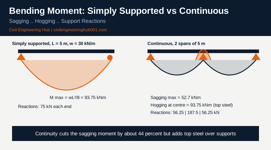
The best way to see the difference is to run the numbers. Take a beam with a 5 m span and a factored uniform load of 30 kN/m, once as a single simply supported span and once as two equal 5 m spans on three supports.
| Check | Simply supported | Continuous (two equal spans) |
|---|---|---|
| Span L and design load w | 5.0 m and 30 kN/m | 2 x 5.0 m and 30 kN/m |
| Maximum sagging moment | 93.75 kNm (wL²/8) | 52.7 kNm (9wL²/128) |
| Hogging moment at centre support | None | 93.75 kNm (wL²/8) |
| End support reaction | 75 kN | 56.25 kN (3wL/8) |
| Centre support reaction | Not applicable | 187.5 kN (5wL/4) |
| Midspan deflection factor | 5wL⁴/384EI | wL⁴/185EI in each span |
Notice what happened. The sagging moment dropped by about 44 percent, from 93.75 kNm to 52.7 kNm. But the support now carries a hogging moment equal to the old midspan moment, and the centre column picks up 187.5 kN, which is 2.5 times the reaction on an end support.
That is why the column and foundation under a middle support are often larger than the ones at the ends. A QS measuring the frame will see it in the concrete and steel quantities. A site engineer will see it in the pad footing sizes.
What do BS 8110 and Eurocode 2 say about continuous beams?
Full moment distribution is accurate but slow, so codes give shortcuts. BS 8110 Part 1, Table 3.5, lets you use bending moment and shear coefficients for continuous beams with three or more spans, provided the spans are approximately equal, the load is substantially uniform, and the characteristic imposed load does not exceed the characteristic dead load. Span lengths should not differ by more than 15 percent of the longest span.
| Location | Moment coefficient | Shear coefficient |
|---|---|---|
| Outer support (continuous) | -0.04FL | 0.45F |
| Middle of end span | 0.09FL | None |
| First interior support | -0.11FL | 0.60F |
| Middle of interior span | 0.07FL | None |
| Other interior supports | -0.08FL | 0.55F |
Here F is the total design ultimate load on the span (1.4Gk + 1.6Qk) and L is the effective span. Compare 0.09FL to the 0.125FL of a simply supported beam and you can see where the saving comes from.
Eurocode 2 (EN 1992-1-1) allows elastic analysis with limited redistribution, normally up to 30 percent for continuous beams where the neutral axis depth ratio is controlled. Kenyan practice still leans heavily on BS 8110 and the Kenya Building Code requirements enforced through the NCA and county approvals, while larger projects increasingly specify the Eurocodes. Always confirm which code the project drawings and specification call up.
Deflection control also favours continuity. BS 8110 Table 3.9 gives basic span to effective depth ratios of 20 for a simply supported beam, 26 for a continuous beam and 7 for a cantilever. Eurocode 2 Table 7.4N gives similar logic, with the end span of a continuous beam allowed a higher ratio than a simply supported one.
In practice, that means a 6 m continuous beam can be about 230 mm deep where a simply supported one with the same load needs about 300 mm. Over a whole floor that is real concrete saved.
Where does the reinforcement go on site, and what goes wrong?
Detailing is where the theory meets the bar bender. If a continuous beam is detailed or fixed like a simply supported one, the top of the beam over the support cracks and, in a bad case, the member fails in hogging.
| Location | Steel required | What to check on site |
|---|---|---|
| Midspan | Bottom main bars (tension) | Cover to bottom bars, spacers every 1 m |
| Over intermediate support | Top bars (tension) | Bar size and number against drawing, top cover |
| Bottom bars at support | Anchorage and lapping bars | Minimum anchorage length into the support |
| Near supports | Closer link spacing | Links at drawn spacing, not evenly spread |
| Top bar curtailment | Extend about 0.3L from the support face | Do not stop top bars short |
Here are the mistakes that show up again and again:
- Top bars over the central column cut short or left out because the fixer assumed the beam was simply supported.
- Top bars pushed down during concreting, which reduces the effective depth where the hogging moment is highest.
- Props struck too early from one span, which changes the load path before the concrete has gained strength.
- Construction joints placed over the support instead of in the middle third of the span, where shear is lowest.
Also remember the settlement effect. Continuous beams are sensitive to uneven foundation settlement because a sinking support changes the moments in both adjacent spans. Check that the footings under every support were built to the same founding level and bearing strata.
The same logic applies to architects and MEP teams. Services that pass through a continuous beam must stay out of the support zones, where shear and hogging steel are concentrated. Always get sleeve positions approved by the structural engineer first.
Frequently Asked Questions
Q: Is a continuous beam always better than a simply supported beam?
Not always. Continuous beams use less concrete and steel, but they need good foundations and accurate detailing over the supports. Precast and short single span members are simpler as simply supported units.
Q: Why does a continuous beam have top steel over the supports?
Because the beam hogs over the supports, which puts the top face in tension. Concrete is weak in tension, so the top steel must carry it. Without it, wide cracks form on the top of the beam right above the column.
Q: Can I treat a two span beam with the BS 8110 coefficients?
Not directly. Table 3.5 is intended for three or more approximately equal spans. For two spans you should use elastic analysis, moment distribution or software such as PROKON, and then check the supports and spans separately.
Conclusion
Simply supported beams are easy to analyse and build, but they carry the full wL²/8 at midspan. Continuous beams share the load between sagging and hogging zones, save material and reduce deflection, as long as the top steel and the foundations are right.
Next time you pick up a structural drawing, look first at how the beam is supported. That one detail tells you where the tension is and where the bars must go.
Want more practical construction knowledge delivered directly to you?
Subscribe to our YouTube channel: https://www.youtube.com/@TheCivilEngineeringHub-001
PS: Join our engineering WhatsApp community for daily learning at +254731393520