

Walk onto any active site in Nairobi and you will find two types of people: those who can read a structural drawing and those who are just following instructions. The truth is, knowing how to read a structural drawing is what separates a site engineer who can catch an error before it becomes a demolition, from one who finds out after the concrete has cured.
In simple terms, a structural drawing tells you exactly what size, shape, position and reinforcement every column, beam and slab in a building needs to have. It is the engineer’s instruction manual for the frame that holds the entire structure up. Miss a detail on that drawing, and you are not just making a paperwork error. You are gambling with the safety of the building.
Quick Answer: To read a structural drawing, start with the column layout and grid lines, then move to beam schedules for reinforcement sizes, then slab plans for mesh and bar spacing. Cross-check every dimension against the architectural drawing before construction begins.
What Makes Up a Structural Drawing Set
A complete structural drawing set is not one sheet. It is a package, and each sheet answers a different question on site.
Honestly, most site confusion happens because someone is reading the wrong sheet for the wrong question. A foundation plan will not tell you beam reinforcement. A column schedule will not tell you slab thickness. Know which sheet answers which question, and half your site problems disappear.
A standard set typically includes: general notes and specifications, foundation layout plan, column layout plan (grid), beam layout and schedule, slab reinforcement plan, and detail sheets for connections, staircases and special elements. Kenyan structural drawings prepared under the Engineers Board of Kenya (EBK) registration requirements will also reference the design code used, usually BS 8110 or increasingly Eurocode 2 (EC2).
How to Identify Columns on a Structural Drawing
Columns appear on the drawing as small rectangles or squares positioned at the intersection of grid lines. Each column carries a label, something like C1, C2 or C-A1, that ties it back to a column schedule on a separate sheet.
That column schedule is where the real information lives. It tells you the column size in millimetres, the number and diameter of main reinforcement bars, the link (stirrup) size and spacing, and the concrete grade required, usually expressed as C25, C30 or similar.
On site, the mistake most artisans make is reading only the drawing plan and ignoring the schedule. A column marked C1 on the plan means nothing on its own. You need the schedule to know it is, for example, 300mm x 300mm with 4No. Y16 bars and Y8 links at 200mm centres. That means the column is 300 millimetres square, has four main reinforcement bars each 16mm in diameter, and stirrups (links) made from 8mm bars spaced every 200 millimetres.
How to Read Beam Callouts and Reinforcement Details
Beams run between columns and are labeled similarly, usually as B1, B2 and so on, referencing a beam schedule. That means every beam callout you see on a layout plan is shorthand for a full set of instructions found elsewhere in the drawing set.
A beam schedule will typically show the beam’s overall size (width x depth), top reinforcement, bottom reinforcement, and shear link spacing, which often changes along the beam’s length. This is because bending moments and shear forces are not uniform. Near the supports, shear is highest, so links are closer together. Near mid-span, they can be spaced further apart.
This is where classroom theory and site practice must connect. Applied Mathematics and structural analysis units teach you why the reinforcement pattern changes along a beam. Reading the drawing correctly on site is where that theory becomes real, because if the closer link spacing near supports is ignored, the beam becomes vulnerable to shear failure exactly where it is most likely to occur.
| Symbol / Abbreviation | Meaning | Where You’ll See It |
|---|---|---|
| C1, C2, C3 | Column reference number | Column layout plan |
| B1, B2, B3 | Beam reference number | Beam layout plan |
| Y16, Y12, Y8 | High yield deformed bar, diameter in mm | Column, beam and slab schedules |
| R8, R10 | Mild steel round bar, diameter in mm | Links and secondary reinforcement |
| T & B | Top and Bottom reinforcement | Beam and slab sections |
| c/c | Centre to centre spacing | Bar and link spacing notes |
| GL | Ground Level | Foundation and section drawings |
| FFL | Finished Floor Level | Slab and section drawings |
Understanding Slab Drawings and Reinforcement Layout
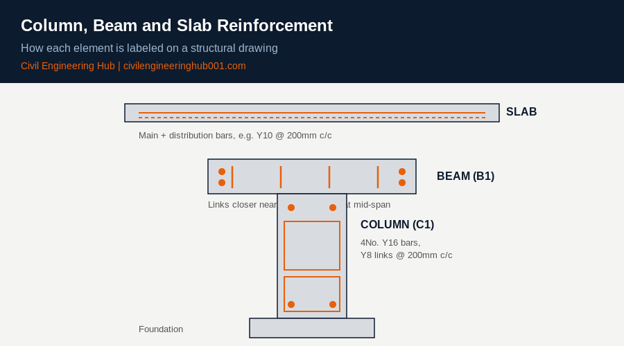
Slab drawings show reinforcement as a mesh pattern of parallel lines running in two directions, typically labeled main bars and distribution bars. The main bars carry the primary load and span the shorter direction in a one-way slab, while distribution bars control cracking and share load in the secondary direction.
For a two-way slab, you will see main reinforcement running in both directions because the slab is supported on all four sides and shares load across both spans. That means the callout will specify bar size and spacing separately for each direction, something like Y10 @ 200mm c/c both ways.
A detail Kenyan site supervisors must watch closely is the concrete cover. The Kenya Building Code and BS 8110 both specify minimum cover requirements to protect reinforcement from corrosion, typically 20mm to 25mm for slabs in normal exposure and up to 40mm or more for foundations and elements exposed to weather. Skimping on cover is one of the most common and costly site shortcuts, because it shows up years later as rust stains and spalling concrete.
Structural vs Architectural Drawings .. Why the Distinction Matters
A structural drawing and an architectural drawing describe the same building from two completely different angles, and confusing them causes real site problems.
| Aspect | Architectural Drawing | Structural Drawing |
|---|---|---|
| Primary Purpose | Shows spaces, finishes and appearance | Shows load-bearing elements and reinforcement |
| Column/Beam Detail | Shown as outline only | Shows exact size, bars and links |
| Who Uses It Daily | Architect, interior designer, finishing crew | Structural engineer, steel fixer, site supervisor |
| Level of Dimension Detail | Room sizes, door and window positions | Millimetre-level reinforcement and concrete detail |
When the two sets disagree, and on real projects they sometimes do, the structural drawing takes precedence for anything related to the frame, foundations and load-bearing elements. This is a professional judgment call, and it is exactly why an RFI (Request for Information) process exists. Raise it in writing to the structural engineer, do not guess on site.
A Practical Site Checklist for Reading Structural Drawings
The truth is, most site engineers do not read a structural drawing in one pass. They work through it in a sequence, because reading everything at once leads to missed details. Here is the order that works on real Kenyan sites, from foundation to slab.
| Step | What To Check | Why It Matters |
|---|---|---|
| 1 | Confirm grid lines match the architectural set | Prevents columns landing in the wrong position |
| 2 | Read the foundation plan and footing schedule | Sets the base that everything above depends on |
| 3 | Cross-check column sizes against the column schedule | Confirms reinforcement and concrete grade before casting |
| 4 | Trace beam reinforcement from support to mid-span | Link spacing changes along the beam, easy to miss |
| 5 | Check slab bar direction and spacing | One-way and two-way slabs need different bar layouts |
| 6 | Verify concrete cover on every element | Protects reinforcement from corrosion long-term |
| 7 | Note the design code referenced in the general notes | BS 8110 and EC2 have different detailing rules |
This is exactly why experienced structural engineers insist on mastering detailing before advancing into full design work. You cannot design what you cannot first read and interpret accurately, and that discipline is built one drawing at a time.
For students revising Perform Structural Design Analysis or Conduct Material Testing units, this checklist also mirrors how practical exam scenarios are graded. Examiners are not just checking whether you know the formula. They are checking whether you can trace a real drawing from grid line to reinforcement detail without missing a step.
Frequently Asked Questions
Q: What is the difference between a structural drawing and a shop drawing?
A structural drawing is prepared by the structural engineer and shows design intent, sizes and reinforcement requirements. A shop drawing, often called a bar bending schedule or fabrication drawing, is prepared afterward to guide the actual cutting and bending of steel on site. In simple terms, the structural drawing tells you what is needed, the shop drawing tells the steel fixer exactly how to produce it.
Q: Can a mason or site supervisor without an engineering degree learn to read structural drawings?
Yes, and honestly, they should. Understanding column and beam callouts, reinforcement symbols and cover requirements makes any site professional more valuable and reduces costly errors. It does not replace an engineer’s design judgment, but it builds the shared language every construction team needs.
Q: What should I do if the structural drawing and architectural drawing do not match?
Stop and raise a Request for Information (RFI) to the structural engineer before proceeding. Never resolve a structural versus architectural conflict by site guesswork, because structural elements affect the safety of the entire building. The structural drawing generally governs for frame and reinforcement matters.
The Bottom Line
Reading a structural drawing is a skill, not a talent you are born with. It comes from repetition: cross-checking column schedules against layout plans, tracing beam reinforcement from support to mid-span, and understanding why slab bars run the way they do.
Master this one skill and you immediately become more useful on any site, whether you are a civil engineer, structural engineer, site supervisor or artisan. The drawing is the plan. Your job is to make sure what gets built actually matches it.
Want more practical construction knowledge delivered directly to you?
Subscribe to our YouTube channel: https://www.youtube.com/@TheCivilEngineeringHub-001
PS: Join our engineering WhatsApp community for daily learning at +254731393520