

Walk onto any electrical fit-out site in Nairobi and you will find one drawing that decides how fast the team moves.. the electrical single-line diagram. The truth is, most site teams treat it as “the electrician’s drawing” and never learn to read it themselves. That is a mistake, because the SLD tells you where power comes from, how it is protected, and what happens if something fails.
In simple terms, a single-line diagram (SLD) is a simplified schematic that shows an entire electrical distribution system using single lines instead of drawing every conductor. It shows the path of power from the utility source, through the main switchboard, down to sub-boards, and finally to individual loads. Every civil engineer, structural engineer, architect, quantity surveyor and site supervisor should be able to read one, because power routing affects conduit runs, riser shafts, and load-bearing penetrations.
This matters even more on multi-storey developments, where the SLD is one of the first drawings that shapes how risers, service ducts and plant rooms are planned. If your team only looks at it during first fix, you have already lost the chance to catch conflicts early.
Quick Answer: An electrical single-line diagram (SLD) shows the full path of power distribution in a building using simplified symbols and single lines. Reading one means tracing the flow from the utility connection through protection devices to each load, while checking ratings, cable sizes and switchgear against the schedule.
What Is an Electrical Single-Line Diagram and Why It Matters On Site
An SLD is not a wiring diagram. It does not show every phase conductor, neutral and earth individually. Instead it uses one line to represent a full circuit, with symbols marking transformers, breakers, meters and distribution boards. This makes it the fastest way to understand how a building gets and distributes electricity.
On site, the SLD matters because it drives decisions outside the electrical scope. Riser shaft sizing, fire-rated penetrations, and even structural openings for busbar trunking all trace back to what the SLD shows. Honestly, a site supervisor who cannot read an SLD will struggle to coordinate services with the structural and architectural teams during a services coordination meeting.
The Basic Symbols You Must Know Before Reading Any SLD
Symbols on an SLD follow IEC 60617, the international standard for graphical symbols used in electrical diagrams. Kenyan consultants generally follow this standard alongside BS 7671 (IET Wiring Regulations) for design practice, since Kenya does not yet have a fully independent national wiring code and leans on British and IEC standards through KEBS adoption.
| Symbol | What It Represents | Where You Will See It |
|---|---|---|
| Rectangle with diagonal line | Circuit breaker or isolator | Main switchboard, sub-boards |
| Circle with “M” | Motor connection | Pump rooms, lift machine rooms |
| Triangle inside circle | Transformer | Substation, main intake |
| Zigzag line | Fuse | Distribution boards |
| Circle with “kWh” | Energy meter | Utility intake point, tenant metering |
Learn these five symbols first before anything else. Once you can spot a breaker, a transformer and a meter at a glance, the rest of the diagram becomes far easier to follow, because most SLDs are just repeated combinations of these basic elements arranged in a hierarchy.
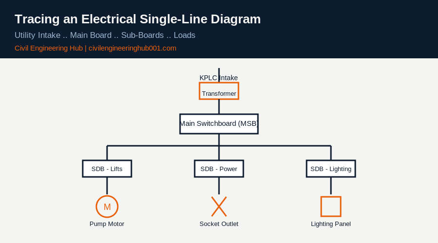
How to Trace Power Flow From Source to Load
Start at the utility connection point, usually shown at the top left of the diagram, marked as the Kenya Power (KPLC) intake or an in-house transformer for larger developments. From there, follow the single line down to the main switchboard (MSB). This is where the incoming supply is metered, protected by a main breaker, and split into outgoing ways.
Each outgoing way feeds either a sub-distribution board (SDB) or a direct load such as a lift, water pump, or HVAC unit. That means every branch you trace should end at a labelled load. If a line on the SLD does not terminate at a clearly labelled device, flag it as a query on your RFI log before construction proceeds. Do not assume the gap will resolve itself during installation.
For buildings with standby power, the SLD will also show an automatic transfer switch (ATS) between the utility supply and the generator. Trace this section carefully, because the changeover logic determines which loads are on the essential circuit and which are not, and that decision affects your generator sizing and fuel budget.
Reading Protection Devices, Ratings and Cable Sizes on the Diagram
Every breaker or fuse on the SLD carries a rating, usually shown as a number next to the symbol, for example “100A” or “63A”. These ratings must match the cable size feeding that circuit, which is usually referenced separately in the cable schedule that accompanies the SLD.
| Component | Typical Rating Shown | What To Check On Site |
|---|---|---|
| Main breaker | Amperage (e.g. 400A) | Matches transformer or utility supply capacity |
| Sub-board breaker | Amperage (e.g. 63A, 100A) | Matches cable cross-section in schedule |
| Earth leakage device | Sensitivity in mA (e.g. 30mA) | Fitted on circuits serving wet areas |
| Cable size | mm² cross-section | Matches conduit or trunking size allowed for |
In simple terms, if the breaker rating and cable size on the SLD do not match what is specified in the cable schedule, that is a design coordination error, and it needs to be raised before the cables are pulled. Catching this on paper costs nothing. Catching it after installation costs a full re-pull.
A Practical Site Checklist for Reading an SLD Before Installation Begins
Before switchgear is ordered or first fix begins, run through this sequence with the site team. It takes less than an hour and prevents costly rework later in the programme.
| Step | What To Verify |
|---|---|
| 1 | Confirm the SLD revision matches the current drawing register issue |
| 2 | Trace every branch from the main board to confirm it ends at a labelled load |
| 3 | Cross-check breaker ratings against the cable schedule |
| 4 | Confirm riser shaft positions match the structural drawing set |
| 5 | Verify earth leakage protection is shown for all wet area circuits |
Common Mistakes Site Teams Make When Interpreting SLDs
The most common mistake is reading the SLD in isolation from the architectural and structural drawings. A riser shaft shown on the SLD must physically exist at the same location on the structural drawing, with adequate fire-rated sealing once services pass through. If the shaft has moved during design development, the SLD needs to be reissued.
The second common mistake is ignoring revision numbers. An SLD is a living document during design development, and an outdated copy on site can lead to wrong breaker sizes being ordered. Always confirm the revision code in the title block matches the latest issue on the drawing register before ordering switchgear.
The third mistake, seen often on smaller Kenyan projects, is skipping the SLD entirely and working straight from a verbal brief. This might save time on paper, but it removes the one document that shows the full protection logic of the building, and it leaves no reference when a fault needs tracing months later.
How an SLD Connects to the Rest of the Electrical Drawing Set
The SLD works together with the layout drawings (showing physical positions of boards and outlets), the cable schedule (showing sizes and lengths), and the load schedule (showing connected load per circuit). Reading the SLD alone gives you the logic of the system. Reading it alongside these other documents gives you the full picture needed to install correctly.
For quantity surveyors, the SLD is also a measurement tool. It tells you how many distribution boards, breakers and metering points to price in the BOQ, which is why QS teams should never price an electrical BOQ without cross-checking it against the SLD first.
Frequently Asked Questions
Q: Is an SLD the same as a wiring diagram?
No. An SLD is a simplified schematic showing the logic of power distribution using single lines and symbols. A wiring diagram shows the actual physical conductors, terminals and connections in detail. Site electricians use both, but the SLD is the reference for overall system design and coordination.
Q: Who is responsible for producing the SLD on a project?
The electrical engineer or MEP consultant produces the SLD as part of the design deliverables. On smaller projects in Kenya, this may be prepared by a registered electrical contractor working with the architect, but it should still be reviewed by a qualified electrical engineer before construction.
Q: What standard governs electrical single-line diagram symbols?
IEC 60617 is the international standard for graphical symbols used in single-line diagrams, and it is widely referenced in Kenyan practice alongside BS 7671 (IET Wiring Regulations). KEBS has adopted several IEC and BS standards for local electrical installation practice, so always confirm which standard the consultant has specified for your project.
Conclusion
An electrical single-line diagram is not just an electrician’s tool. It is a coordination document that every construction professional on a project should be able to read, because it affects riser shafts, structural openings, BOQ pricing and installation sequencing. The truth is, teams that read the SLD together, early, avoid the costly clashes that show up during first fix.
Want more practical construction knowledge delivered directly to you?
Subscribe to our YouTube channel: https://www.youtube.com/@TheCivilEngineeringHub-001
PS: Join our engineering WhatsApp community for daily learning at +254731393520