

A plumbing layout drawing tells you where every pipe, fitting, valve and fixture goes before a single trench is dug or a wall is plastered. If you can read it, you can set out the work correctly, order the right materials and spot clashes with the structure early. If you cannot, you end up chiselling finished beams and redoing screeds.
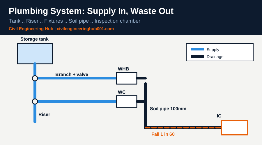
In simple terms, a plumbing layout is a map of clean water going in and waste water going out. To read it, start with the legend, separate the supply system from the drainage system, then follow each line from its source to the fixture using the pipe sizes, levels and symbols shown.
The truth is, most plumbing mistakes on site are not skill problems. They are drawing problems.. someone skipped the legend, misread a gradient or never checked the plumbing sheet against the structural plan. This guide shows you how to read the drawing step by step, with the standards and site habits that matter in Kenya.
Quick Answer: To read a plumbing layout drawing, check the legend and scale first, separate the water supply lines from the drainage lines, then trace each line from source to fixture while confirming pipe sizes, gradients and levels against the schedule and the structural drawings.
What does a plumbing layout drawing actually show?
A plumbing drawing set is rarely one sheet. It is a group of drawings, each answering a different question. Floor plans show where pipes run horizontally, riser diagrams show how water and waste move between floors, and detail drawings show how a connection is built.
Honestly, the riser diagram is the sheet most people ignore, yet it explains the whole system in a single view. Read it before you read the floor plans.
| Drawing type | What it shows | Who uses it most |
|---|---|---|
| Floor plan layout | Fixture positions, horizontal pipe routes, shafts | Plumber, site engineer |
| Riser diagram | Vertical pipes, floor to floor connections, valves | Plumber, MEP coordinator |
| Drainage layout | Soil and waste lines, inspection chambers, falls | Foreman, drainage gang |
| Detail drawings | Trap, manhole, tank and valve connections | Plumber, inspector |
| Fixture schedule | Type, size and quantity of each fixture | Quantity surveyor, store keeper |
On a typical Kenyan residential or commercial job, the plumber, the site engineer and the architect all work from the same set. Agree early which sheet controls when two drawings disagree. Usually the latest revision of the plumbing drawing controls pipe routes, while the architect’s drawing controls fixture positions.
How do you read the legend, symbols and abbreviations first?
Every plumbing drawing has a legend, and it is the first thing you should read. Symbols are not universal. One designer’s dashed line is cold water, another designer uses the same line for a vent pipe. Never assume.
The legend also tells you the scale, the pipe material and the standard being followed. Check the scale before you measure anything off the sheet, because a pipe length taken from the wrong scale gives a wrong material order and a wrong cost.
| Line or symbol | Typical meaning | What to confirm on site |
|---|---|---|
| Thin solid line, often blue | Cold water supply | Pipe material and pressure rating |
| Thin solid or dashed line, often red | Hot water supply | Insulation and spacing from the cold line |
| Thick solid line | Soil pipe from WC | Diameter, gradient, access points |
| Dotted line | Vent or waste branch (varies by designer) | Read the project legend |
| Valve symbol on a line | Gate or isolating valve | Position and easy access |
| IC or RE label | Inspection chamber or rodding eye | Cover level and depth |
Abbreviations carry just as much information. WC is water closet, WHB is wash hand basin, FT is floor trap, SVP is soil and vent pipe, IC is inspection chamber and IL is invert level. If an abbreviation is not on the legend, ask the designer. A guess on a buried drain is expensive to fix.
In practice, print the legend on a small card and keep it with the drawing set. Plumbers and foremen work faster when they do not have to hunt for it on a crowded sheet.
How do you read pipe sizes, gradients and levels?
Pipe sizes are written next to each line, for example 100mm uPVC. Supply pipes are sized for flow and pressure, while drainage pipes are sized for the discharge they carry and must also fall at the right gradient so waste moves by gravity.
For drainage inside buildings, designers commonly follow BS EN 12056 for gravity systems, and BS EN 806 for drinking water installations. In Kenya, these sit alongside the Kenya Building Code and the requirements of the county public health and planning departments. The project specification always has the final word.
| Pipe size | Typical minimum gradient | Typical use |
|---|---|---|
| 40 to 50mm | 1 in 40 | Basin, sink and shower waste |
| 100mm | 1 in 40 to 1 in 60 | Soil pipe and WC branches |
| 150mm | 1 in 60 to 1 in 80 | Main building drain |
These are typical design values for orientation only. Always use the gradient written on your drawing.
Levels are where many people get lost. Cover level (CL) is the top of the chamber cover. Invert level (IL) is the inside bottom of the pipe. Chamber depth is simply CL minus IL. For example, CL 1650.40 and IL 1648.90 gives a depth of 1.50 m.
To check the fall between two chambers, divide the length by the gradient figure. A 12 m run at 1 in 60 drops 0.20 m, so if the upstream IL is 1648.90, the downstream IL must be 1648.70. If your levels do not match this, something on the drawing or in the trench is wrong.
How do you trace water supply from the source to the fixtures?
Supply lines are easiest to read when you follow the water the way it travels. Start at the source and move one stage at a time until you reach the last tap on the drawing.
| Step | What to find on the drawing | Question to ask |
|---|---|---|
| 1. Source | County water meter, borehole or storage tank | Where does the building connect? |
| 2. Rising main | Main pipe and isolating valve | What size and material is it? |
| 3. Storage | Ground or roof tank, float valve, overflow | Is capacity enough for the occupants? |
| 4. Distribution | Vertical risers in shafts | Which floors does each riser serve? |
| 5. Branches | Horizontal pipes to each bathroom or kitchen | Are isolating valves provided? |
| 6. Hot water | Heater, solar panel or boiler connection | Where is the hot line separated from cold? |
In Kenya, intermittent supply means many buildings depend on storage tanks. That makes tank height important, because water pressure at the fixtures comes mostly from the height of the tank above them. If the tank sits too low, the top floor taps will run weakly, and no pipe size will fix that.
Also check where the overflow and washout pipes discharge. A tank overflow that ends nowhere useful will stain a wall or flood a roof within weeks.
How do you check the plumbing drawing against architectural and structural drawings?
A plumbing drawing is never read alone. Pipes pass through beams, slabs and walls, and each of those belongs to someone else’s drawing. This is where site coordination saves money.
Holes through structural members must be approved by the structural engineer. Under BS 8110 and Eurocode 2 detailing principles, openings in beams are only allowed in zones the engineer has checked, and they must never be chiselled after concreting. Sleeves are cast in before the pour, so the plumber must be on site on casting day.
Before work starts on any floor, walk through this checklist with the foreman and the plumber:
- Fixture positions on the plumbing sheet match the architectural floor plan and the room dimensions.
- Shafts and ducts are large enough for the pipes, valves and access shown.
- Slab drops or recesses for wet areas are shown on the structural drawing, so floor traps will fall correctly in the screed.
- Sleeve positions through beams and slabs are marked and approved before the formwork is closed.
- Drain routes avoid foundation footings, or the footing is lowered or bridged as the engineer directs.
- Inspection chambers are not located under planned parking slabs, gates or tree positions.
The most common site error is a drain line clashing with a pad footing or a ground beam. Catching it on paper takes ten minutes. Catching it in the trench costs a day of rework and sometimes an engineer’s variation.
Finally, keep a marked up set of as built drawings. When the plumber changes a route on site, record it the same day. Future repairs, and the client’s handover file, depend on it.
Frequently Asked Questions
Q: What is the difference between a plumbing layout and a drainage layout?
A plumbing layout usually covers the clean water supply, hot and cold lines, and fixture connections inside the building. A drainage layout covers the soil and waste pipes, inspection chambers and the connection to the sewer or septic tank. On many projects both appear on the same sheet, so use the legend to tell the two systems apart.
Q: What minimum gradient should a 100mm soil pipe have?
Designers commonly use between 1 in 40 and 1 in 60 for a 100mm soil pipe, depending on the flow and the standard being followed. Too steep and the water runs off leaving solids behind, too flat and the pipe blocks. Always use the gradient written on the project drawing and confirm it with the engineer if it looks unusual.
Q: Who approves plumbing drawings in Kenya?
Plumbing and drainage drawings are normally submitted with the building plans to the county planning and public health departments for approval. The design is prepared by a registered professional, and the works are carried out by a contractor registered with the National Construction Authority. Check your county’s current submission requirements, because they can differ.
Conclusion
Reading a plumbing layout drawing is a habit, not a talent. Read the legend, separate supply from drainage, trace every line from source to fixture, verify the gradients and levels, then check everything against the architectural and structural sheets before work begins.
Do this consistently and you will prevent most of the rework that eats site budgets. Whether you are an engineer, an architect, a foreman or a plumber, the drawing is your shared language. Learn to read it well, and the whole team builds faster.
Want more practical construction knowledge delivered directly to you?
Subscribe to our YouTube channel: https://www.youtube.com/@TheCivilEngineeringHub-001
PS: Join our engineering WhatsApp community for daily learning at +254731393520