

A beam does not only fail by bending. It can also fail in shear, with diagonal cracks opening near the supports and very little warning. Shear links are the reinforcement that stops this, and their spacing is one of the most important details on any structural drawing.
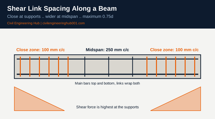
In simple terms, shear links are closed stirrups that wrap the main bars and hold the concrete together across diagonal cracks. Their spacing follows the shear force: closer near the supports where shear is highest, wider towards midspan where it drops. Under both BS 8110 and Eurocode 2, the maximum longitudinal spacing for vertical links is 0.75d, where d is the effective depth of the beam.
This guide explains how link spacing is determined, how the two codes differ, and what goes wrong on Kenyan sites when the bar bender and the carpenter are rushing to beat the concrete truck.
Quick Answer: Shear link spacing is calculated from the design shear force at the support, divided by the beam section and the link steel strength. It must never exceed 0.75d, and it is tightest near the supports where shear is highest.
What do shear links actually do inside a reinforced concrete beam?
When a beam carries load, the shear force pulls the concrete apart along diagonal planes, usually at about 45 degrees. Concrete is weak in tension, so without steel crossing those planes the crack simply opens up. The links cross the crack and stitch the two sides together.
Think of a truss. The concrete acts as the diagonal compression struts, and the links act as the vertical tension ties. If the ties are too far apart, a crack can run between two links without meeting any steel at all.
The truth is that links do more than resist shear. They also hold the main bars in position during pouring, confine the concrete in the compression zone, and keep the top bars from buckling outwards. A beam with good links behaves in a ductile way, and that matters for safety.
Shear is highest at the face of the supports, so that is where the drawings show the closest spacing. On a typical Nairobi frame, you will see links at 100 or 150 mm centres for the first one to two metres, then opening to 200 or 250 mm through the middle.
How does BS 8110 set the shear link spacing?
BS 8110 Part 1, Clause 3.4.5, works from the design shear stress, v = V / (b x d). You compare it with the concrete shear capacity vc from Table 3.8, which depends on the tension steel percentage (100As/bd), the effective depth and the concrete grade. The result tells you which of three situations you are in.
| Condition | What BS 8110 requires | Link rule |
|---|---|---|
| v less than 0.5vc | Links not required by calculation | Nominal links still provided in beams |
| 0.5vc to (vc + 0.4) | Minimum links | Asv/sv at least 0.4b / (0.95 fyv) |
| (vc + 0.4) up to the limit | Designed links | Asv/sv at least b (v – vc) / (0.95 fyv) |
| v above 0.8 times root fcu (max 5 N/mm2) | Section too small | Increase b or d, or raise the concrete grade |
In that table, Asv is the cross-section area of all legs of one link, sv is the spacing along the beam, b is the beam width and fyv is the characteristic strength of the link steel.
Two spacing limits apply on top of the calculation. Longitudinally, sv must not exceed 0.75d. Across the width, no tension bar should be more than 150 mm from a vertical leg of a link, which is why wide beams need an extra inner link or a four-leg arrangement.
Honestly, this second rule is the one most often missed in the office and on site. A 300 mm wide beam with four main bars and a single two-leg link can leave a bar unrestrained.
How does Eurocode 2 treat shear links differently?
EN 1992-1-1 uses a variable strut inclination method instead of a fixed 45 degree truss. The designer chooses an angle theta, with cot theta between 1.0 and 2.5, and checks the link capacity against the design shear force VEd. A flatter strut can reduce the links required, but it also loads the concrete strut harder, so the engineer must check both.
More Kenyan consultancies now design to the Eurocodes, while many older drawings, and many contractors, still think in BS 8110. A site engineer should be comfortable reading both.
| Item | BS 8110 | Eurocode 2 |
|---|---|---|
| Concrete shear check | v compared with vc | VEd compared with VRd,c |
| Link capacity | Fixed 45 degree truss | VRd,s = (Asw/s) z fywd cot theta |
| Minimum links | 0.4b / (0.95 fyv) | rho w,min = 0.08 root fck / fyk |
| Maximum spacing along beam | 0.75d | 0.75d for vertical links |
| Transverse leg spacing | Tension bar within 150 mm of a leg | Not more than 0.75d or 600 mm |
Whatever the code, the site message is the same. The drawing already contains the designer’s decision, and your job is to build exactly that spacing, in exactly that zone.
How do you work out shear link spacing step by step?
Take a simply supported beam, 230 mm wide and 450 mm deep, with an effective depth d of 400 mm. Concrete is C25 (fcu = 25 N/mm2), the tension steel gives 100As/bd = 1.0, and the design shear force at the support face is 150 kN. The steps below follow BS 8110.
| Step | Calculation | Result |
|---|---|---|
| 1. Shear stress | v = 150,000 / (230 x 400) | 1.63 N/mm2 |
| 2. Concrete capacity | vc from Table 3.8 | About 0.63 N/mm2 |
| 3. Upper limit check | 0.8 x root 25 | 4.0 N/mm2, so section is adequate |
| 4. Which case? | vc + 0.4 = 1.03, and v is greater | Designed links needed |
| 5. Required Asv/sv with R8 (fyv = 250) | 230 x (1.63 – 0.63) / (0.95 x 250) | 0.97 mm2/mm |
| 6. Spacing with two-leg R8 (Asv = 101 mm2) | 101 / 0.97 = 104 mm | Provide R8 at 100 mm |
| 7. Same beam with Y8 (fyv = 460) | 101 / 0.53 = 191 mm | Provide Y8 at 175 mm |
Both answers are below the 0.75d limit of 300 mm, so the limit does not control near the support. Further along the span, where v drops below vc + 0.4, you only need minimum links: 0.4 x 230 / (0.95 x 250) = 0.39 mm2/mm. Two-leg R8 gives 260 mm by calculation, and the 0.75d cap brings it down to 250 mm in practice.
Notice what that example tells you. The same beam needs links at 100 mm with mild steel and 175 mm with high yield steel. This is exactly why swapping bar types on site without the engineer’s approval is a structural decision, not a purchasing decision.
What do site crews get wrong with shear links in Kenya?
Design is only half of the story. A correct calculation means nothing if the cage on site does not match it. These are the mistakes we see most often on residential and commercial frames:
- Uniform spacing everywhere. The bar bender sets one spacing along the full beam because it is faster. The support zones end up under-reinforced.
- First link too far from the support. The first link should sit close to the column face, usually about 50 mm away, as shown on the detail.
- Open or 90 degree hooks. Links should close with 135 degree hooks, alternated from one side to the other along the beam, so they do not all open on the same face.
- Missing links in the beam to column joint. The joint is where shear and moment peak together, yet links are often left out because the column cage is in the way.
- No cover blocks. Links touch the formwork, and the rusting starts within a few years. BS 8110 gives 25 mm nominal cover for mild exposure and 35 mm for moderate exposure, to the outermost steel, which is the link.
The Kenya Building Code and the NCA expect the contractor to build to approved drawings, and inspection by the engineer before concrete is poured is the control that catches these errors. Once the concrete covers the cage, nobody can see what was built.
| Pre-pour check | What to confirm | Who signs off |
|---|---|---|
| Link size and steel type | R8, Y8 or Y10 as per the schedule | Site engineer |
| Spacing zones | Close zone length and centres match the drawing | Site engineer and foreman |
| Hooks and ties | 135 degree hooks, tied at every corner | Foreman |
| Cover | Spacer blocks at all faces | Site engineer |
| Joints | Links present in column and beam junctions | Resident engineer |
Why does this matter to the whole construction team?
Shear links are not only a structural engineer’s concern. The architect needs to know why a beam cannot be cut back in depth, because a shallower beam raises shear stress and demands closer links. The quantity surveyor measures links by weight in the bill of quantities, so spacing directly drives cost.
The electrician and plumber need to understand why a sleeve through a beam near the support is a problem. A hole in the shear zone cuts through the very links holding the beam together, and it must be approved and detailed by the engineer before any core is made.
The mason and carpenter see the cage before and after the formwork closes. If a link is bent out of position by a passing trade, it takes thirty seconds to fix before the pour and is impossible to fix after it.
Frequently Asked Questions
Q: What is the minimum spacing between shear links?
Codes mainly limit the maximum spacing, but practical detailing sets a lower limit. Spacing tighter than about 75 mm makes it hard for concrete and the vibrator to pass through the cage. If the design needs tighter links, the engineer should widen the beam, use larger bars or add legs.
Q: Can I replace R8 links with Y8 links on site?
Only with the engineer’s written approval. Moving from mild steel to high yield steel can allow wider spacing, but moving the other way needs closer spacing. Never change the bar type or the spacing on your own judgment.
Q: Why are links closer near the supports?
The shear force diagram peaks at the supports and falls towards midspan. Closer links give more steel crossing the diagonal cracks where the demand is greatest. Towards midspan the shear is low, so minimum links are enough.
Conclusion
Shear link spacing is not a number to guess. It comes from the design shear force, the beam size, the concrete grade and the link steel, and it is capped at 0.75d under both BS 8110 and Eurocode 2.
On site, the job is simple and demanding at the same time: build the spacing zones exactly as drawn, close the links properly, keep the cover, and inspect before you pour. Get that right, and your beams will carry load the way the designer intended.
Want more practical construction knowledge delivered directly to you?
Subscribe to our YouTube channel: https://www.youtube.com/@TheCivilEngineeringHub-001
PS: Join our engineering WhatsApp community for daily learning at +254731393520