

Every construction professional, from the site electrician to the project engineer, works from the same source of truth: the drawing set. Yet a shocking number of people on site cannot confidently read one.
The truth is.. a drawing is a language. Once you learn its grammar, lines, symbols, scales and notes, you stop guessing and start building exactly what was designed. This matters whether you are a mason laying a foundation, an electrician running conduit, or a site supervisor checking work against design.
In this guide, we break down drawing types, scales, symbols, abbreviations, and how professionals across civil, structural, architectural and MEP disciplines each read the same set differently.
Quick Answer: Reading a construction drawing means understanding what each drawing type shows (plans, sections, elevations, details), decoding the scale, symbols and abbreviations used, and cross-referencing architectural, structural and MEP drawings to build one complete picture of the project.
What Are the Main Types of Construction Drawings?
A typical drawing set for a building project is not one document. It is a collection of drawings, each answering a different question about the same structure.
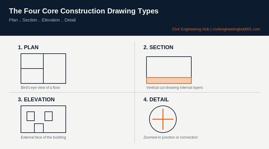
In simple terms, four drawing types carry almost everything you need on a standard job:
| Drawing Type | What It Shows | Who Uses It Most |
|---|---|---|
| Plan | A bird’s eye view of a floor, foundation or roof | All trades |
| Section | A vertical cut through the building showing internal layers | Structural engineers, masons |
| Elevation | An external face of the building from one side | Architects, finishing crews |
| Detail | A zoomed-in view of a specific junction or connection | Structural engineers, fabricators |
A plan alone cannot tell you how deep a foundation sits or how a beam connects to a column. That is what sections and details are for. Honestly.. most site disputes happen because someone read a plan and ignored the section that explained it.
How Do You Read the Scale on a Drawing?
Every drawing is drawn to scale, meaning real dimensions are reduced by a fixed ratio so the whole building fits on a sheet of paper.
A scale of 1:100 means 1 unit on paper equals 100 units on site. So 1cm on the drawing equals 1 metre on the ground. Common scales you will meet on a Kenyan site include:
| Scale | Typical Use |
|---|---|
| 1:1 or 1:5 | Fine construction details, reinforcement bends |
| 1:20 or 1:50 | Room layouts, individual floor details |
| 1:100 | Standard floor plans and elevations |
| 1:200 or 1:500 | Site plans showing the full plot |
| 1:1000 or smaller | Location plans and layout plans |
Never scale a drawing with a ruler to get a dimension for construction. Always use the written dimension. Printers resize PDFs and photocopies shrink paper, so a ruler reading can be wrong by a wide margin. If a dimension is missing, that is what a Request for Information is for, not a guess.
What Do Common Drawing Symbols and Abbreviations Mean?
Drawings are dense with shorthand because there is no room to spell everything out. Learning the common ones is the fastest way to stop feeling lost on a drawing.
| Abbreviation | Meaning |
|---|---|
| DPC | Damp Proof Course |
| FFL | Finished Floor Level |
| GL | Ground Level |
| RC | Reinforced Concrete |
| c/c or CTC | Centre to Centre spacing |
| T&G | Tongue and Groove |
| NTS | Not To Scale |
| WP | Waterproofing |
Beyond text abbreviations, symbols carry meaning too. A hatched pattern usually means concrete or masonry in section. A dashed line often shows something hidden above or below the cut plane, like a beam overhead or a foundation underground. A circle with a number inside is usually a grid reference or a detail callout pointing you to another sheet.
How Should You Approach a New Drawing Set on Site?
When a new drawing set lands on your table, resist the urge to jump straight to the section you think is relevant to you. Work through it in order.
| Step | Action |
|---|---|
| 1 | Read the general notes and legend on the cover or first sheet |
| 2 | Check the revision number and date against the latest issue register |
| 3 | Identify the scale and confirm it against a known dimension |
| 4 | Study the overall plan before zooming into your specific work area |
| 5 | Cross-check your trade’s drawing against the other disciplines’ drawings |
| 6 | Flag anything unclear through a formal Request for Information |
That means by the time you pick up a tool or set out a line, you already understand the full picture, not just your small corner of it. This single habit prevents most of the abortive work seen on Kenyan sites, work done correctly according to an outdated or misunderstood drawing, then demolished and redone.
How Do Architectural, Structural and MEP Drawings Work Together?
The truth is.. no single drawing tells the whole story, and this is where cross-disciplinary teams either work well together or clash on site.
An architectural drawing shows the room layout, finishes and openings. A structural drawing shows the columns, beams, slabs and reinforcement that hold that layout up. An MEP drawing shows the electrical, plumbing and mechanical routes running through both.
When these three do not agree, you get real problems: a plumbing stack clashing with a beam, a light switch positioned inside a column, a door swing blocked by ductwork. That means every professional on site benefits from checking their trade’s drawing against the other two before work starts, not after.
A quantity surveyor reading the same set is looking for something different again: quantities, specifications and provisional items that will end up in the Bill of Quantities. Each profession reads the same paper for a different purpose, and that is exactly why cross-checking matters.
What Standards Govern Construction Drawings in Kenya?
In Kenya, construction drawings for approval must comply with the Kenya Building Code and be prepared and signed off by registered professionals recognised under the National Construction Authority (NCA) and relevant boards such as the Engineers Board of Kenya and the Board of Registration of Architects and Quantity Surveyors.
Structural drawings typically reference design codes such as BS 8110 or Eurocode 2 for reinforced concrete detailing, and these references usually appear in the general notes on the first sheet of a structural drawing set. Always read the general notes before you read anything else. They tell you the concrete grade, the code of practice used, cover requirements, and any project-specific instructions that override standard assumptions.
For county approval in most parts of Kenya, drawings submitted must carry the stamp of a registered architect or engineer, and site supervisors should confirm the drawing in use on site matches the approved, stamped version. An unapproved or superseded drawing on site is one of the most common and costly site errors.
A Practical Example From Site
Picture a mason handed a foundation plan showing a strip footing at 1:100 scale. Without checking the section drawing, the depth and reinforcement detail are invisible on the plan alone. The mason who only reads the plan risks digging to the wrong depth or missing the blinding concrete layer specified in the section.
The mason who checks the plan, the section and the general notes together will know the founding depth, the concrete grade, and whether DPC is required at that level. That is the difference between a five-minute drawing check and a costly redo. In simple terms, the extra few minutes spent cross-referencing drawings is always cheaper than the hours lost correcting work built from an incomplete picture.
Frequently Asked Questions
Q: What is the difference between a working drawing and an as-built drawing?
A working drawing is what you build from. It reflects the design intent before construction starts. An as-built drawing is updated after construction to reflect what was actually built on site, including any approved changes made along the way. Every project should end with an as-built set, because it becomes the reference for future maintenance, renovation or extension.
Q: Why do drawing dimensions sometimes not add up?
This usually happens when a drawing has been revised but not every dimension was updated to match, or when architectural and structural drawings were not properly coordinated. In simple terms, treat any mismatch as a red flag and raise a Request for Information immediately rather than assuming which figure is correct.
Q: Can I use a drawing that has no revision number or date?
No. Every drawing in active use should carry a revision number, date and the issuing professional’s stamp. A drawing without these details cannot be confirmed as the current, approved version, and using it exposes the site to serious rework and liability risk.
Conclusion
Reading a construction drawing is not a talent some people are born with. It is a skill built through repetition, learning the drawing types, respecting the scale, memorising common symbols, and understanding how each discipline’s drawing connects to the next.
Honestly.. the professionals who move fastest from student to site are the ones who treat every drawing as something to interrogate, not just glance at. Start with the general notes, confirm the revision, and cross-check between disciplines before a single block is laid.
Want more practical construction knowledge delivered directly to you?
Subscribe to our YouTube channel: https://www.youtube.com/@TheCivilEngineeringHub-001
PS: Join our engineering WhatsApp community for daily learning at +254731393520