

Every building starts on paper.. or these days, on a screen. The floor plan is the single most referenced drawing on any construction site, and the ability to read it well separates the professionals who lead site meetings from those who stay quiet in them.
In this guide, you will learn how to read architectural floor plans step by step.. from the title block to the gridlines, symbols, and dimensions. In simple terms, reading a floor plan means starting at the title block, confirming the scale, then working through walls, openings, and annotations in a fixed order.
This post serves architects first, but the truth is.. every engineer, quantity surveyor, mason, electrician, plumber, and site supervisor reads the same floor plan every day. Learn it once and you will use it for the rest of your career.
Quick Answer: To read an architectural floor plan, start with the title block to confirm the drawing number, revision, and scale, then work systematically through gridlines, walls, doors, windows, and dimensions. Always cross-check the floor plan against the structural and MEP drawings before setting out or building anything.
The Title Block Is Where Every Drawing Reading Starts
Most beginners jump straight into the drawing. That is the first mistake. The title block.. usually at the bottom right corner.. tells you the project name, drawing number, revision, scale, date, and drawing status.
The revision and status matter most on site. A drawing marked “Preliminary” or “For Tender” is not a construction document. Only build from drawings marked “For Construction”, and always confirm you are holding the latest revision.
Honestly, some of the most expensive site errors in Kenya and beyond come from teams building off a superseded revision. Walls get demolished, openings get re-cut, and the variation claims that follow are painful for everyone.
Confirm the Scale Before You Measure Anything
Architectural floor plans are commonly drawn at 1:100 for general arrangement, 1:50 for detailed room layouts, and 1:20 for sections and details. At 1:100, every 1 cm on paper represents 1 metre on site.
Here is the rule that protects you: never scale dimensions off a printed drawing. Printing and photocopying distort the sheet, which is why most drawings carry a “DO NOT SCALE” note. Use the written dimensions, and if a dimension is missing, raise a request for information (RFI) instead of guessing.
For example, if a corridor width is not dimensioned, do not pull out a scale rule and improvise. One phone call to the architect costs nothing. A corridor built 150 mm too narrow costs a demolition.
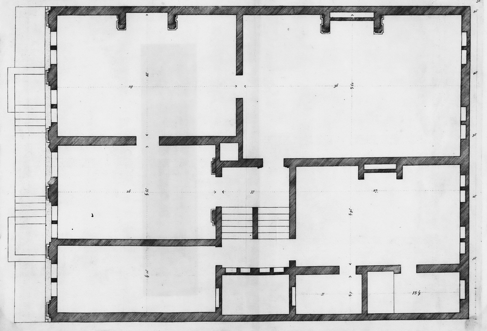
Learn the Standard Floor Plan Symbols
Floor plans use a shared symbol language so that every profession reads the same information. Conventions follow standards like BS 1192 and BS 8541, and approval drawings in Kenya must also satisfy county requirements under the Building Code and NCA project registration rules.
These are the symbols you will meet on almost every sheet:
| Symbol | What It Means On Site |
|---|---|
| Quarter-circle arc on a wall opening | Door leaf and its swing direction.. critical for furniture layouts and electrical switch positions |
| Three parallel lines in a wall | Window.. the outer lines are the wall faces, the inner line is the glazing |
| Filled or hatched rectangle/square | Column.. confirm its size and position on the structural drawings, not the architectural plan |
| Parallel lines with a directional arrow and “UP” | Staircase and its direction of travel from that floor level |
| Circle with a triangle or letter/number tag | Section or elevation marker.. tells you which sheet shows that cut |
| Diagonal cross-hatching between wall lines | Wall material indication, for example masonry versus concrete |
| Dashed lines | Items above the cutting plane, such as beams, bulkheads, or roof overhangs |
A floor plan is a horizontal cut through the building, taken at roughly 1.2 metres above floor level. That is why windows appear but roof beams show as dashed lines.. the cut passes through one and under the other.
Read Dimensions in the Right Order
Dimensions on a floor plan are arranged in chains, from the outside in. Reading them in order keeps you from mixing up structural and finishing measurements.
- Overall dimensions.. the total length and width of the building envelope.
- Grid-to-grid dimensions.. distances between structural gridlines. All setting out starts here, because columns and load-bearing walls are positioned on the grid.
- Wall-to-opening dimensions.. positions of doors and windows along each wall.
- Internal room dimensions.. clear sizes between finished wall faces.
One trap to watch: confirm whether dimensions run to the structural face or the finished face of a wall. A 25 mm plaster allowance on each side changes a room size by 50 mm, and tiling or fitted furniture will expose the error.
Cross-Check the Floor Plan Against Structural and MEP Drawings
The architectural floor plan tells you what the building should look like. The structural drawings tell you what holds it up, and the MEP drawings tell you what runs through it. These three must agree before you build.
On site, the architectural plan governs layouts, finishes, and openings, while the structural drawings govern member sizes and reinforcement. If the architect shows a door where the structural engineer shows a column, neither drawing “wins”.. you raise an RFI and let the design team resolve it on paper.
This is also where related professions meet. The electrician checks door swings before positioning switches, the plumber checks wall thicknesses before chasing pipes, and the QS measures off the same dimension chains for the bill of quantities. One drawing, many readers.
Frequently Asked Questions
Q: What scale are architectural floor plans usually drawn at?
Most general arrangement floor plans are drawn at 1:100, while detailed plans of kitchens, bathrooms, and staircases use 1:50 or 1:20. The title block states the scale, and it can differ from sheet to sheet, so check it every time.
Q: What is the difference between architectural and structural floor plans?
The architectural plan shows spaces, walls, openings, and finishes.. how the building is used. The structural plan shows columns, beams, slabs, and reinforcement.. how the building stands. You need both, and they must be read together.
Q: Can I take measurements directly off a printed floor plan?
No. Printing distorts the sheet, which is why drawings carry a “DO NOT SCALE” note. Use the written dimensions only, and raise an RFI for anything missing.
Conclusion
Reading a floor plan is a fixed routine, not a talent. Title block first, scale second, then gridlines, symbols, dimensions, and a cross-check against the structural and MEP sets. Follow that order on every sheet and you will catch errors before they reach the site.. which is exactly what makes you valuable on any project team.
Want more practical construction knowledge delivered directly to you?
👉 Subscribe to our YouTube channel: https://www.youtube.com/@TheCivilEngineeringHub-001
PS: Join our engineering WhatsApp community for daily learning at +254731393520
Dis awesome