

Quick Answer: An architectural floor plan is a scaled, top-down drawing that shows a building as if it were cut horizontally about 1.2 metres above floor level. It shows walls, doors, windows, room layouts and dimensions, and once you understand its symbols and scale, you can visualize the entire building from a single sheet of paper.
On every project, the floor plan is the first drawing everyone reaches for, but not everyone reads it the same way. An architect sees room relationships and flow. A quantity surveyor sees quantities waiting to be measured. A mason sees where the wall goes tomorrow morning. The truth is, a floor plan carries the same information for everyone. The difference is in how well you can decode it.
If you have ever stood on site holding a set of drawings and struggled to connect what is on paper to what is in front of you, this guide is for you. We will break down what a floor plan actually shows, how to read its symbols and dimensions, and how it connects to structural and MEP drawings. Whether you are a fresh graduate, an artisan, a site supervisor, or an architect early in practice, this is knowledge you need before you touch a single block.
What Exactly Is an Architectural Floor Plan?
In simple terms, a floor plan is a horizontal section. Imagine slicing a building with a flat plane at about 1.2 metres above finished floor level, then looking straight down at what remains. Everything below that cut line, walls, doors, columns, fixed furniture, gets drawn. Everything above it, like a beam soffit or a hanging light, is either omitted or shown as a dashed line.
Floor plans are almost always drawn to scale, most commonly 1:50 or 1:100 for working drawings. In Kenya, drawings submitted for approval to the county government and the National Construction Authority must be prepared by a registered architect or engineer, follow standard scales, and carry the professional’s registration details under the Architects and Quantity Surveyors Act and the NCA Act No. 41 of 2011. That is why an approved floor plan is a legal document, not just a design sketch. Honestly, understanding this early saves you from treating drawings as optional guidance when they are actually the reference every inspection is measured against.
The Core Elements Every Floor Plan Shows
Once you know what to look for, a floor plan stops being a maze of lines. Here is what you should be able to identify on any plan within the first minute of opening it.
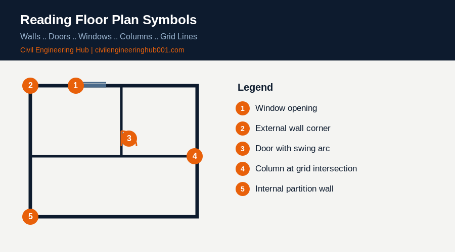
- Walls — shown as thick parallel lines, often hatched or filled solid. External and load-bearing walls are usually thicker than internal partitions.
- Doors — a break in the wall line with a quarter-circle arc showing the swing direction of the door leaf.
- Windows — a break in the wall shown with thin parallel lines, narrower than the wall itself.
- Room names and areas — labelled inside each space, sometimes with the floor area in square metres.
- Grid lines and dimension strings — reference lines labelled with letters and numbers used to locate columns and walls precisely.
- North point — an arrow showing orientation, critical for lighting, ventilation and solar planning.
- Reference tags — codes like D1, W2 or C3 that point to a door schedule, window schedule or finishes schedule for exact sizes and specifications.
| Symbol | What It Represents | Where to Confirm Detail |
|---|---|---|
| Thick solid line, often hatched | External or load-bearing wall | Structural drawing |
| Wall break with quarter-circle arc | Door and its swing direction | Door schedule |
| Thin parallel lines in a wall gap | Window opening | Window schedule |
| Dashed line above the plan view | Overhead feature — beam, roof edge, or soffit | Structural or roof plan |
| Circle or square with a cross or fill | Column | Structural column layout |
| Arrow labelled N | North point and building orientation | Site plan |
Scale, Dimensions and Grid Lines: Getting the Numbers Right
A floor plan without correct dimensions is just an illustration. In simple terms, dimension strings tell you the distance between two points, usually measured from the face of one wall to the face of another, or from grid line to grid line. Never assume a dimension; always read what is written, because plans are not always printed at the exact scale stated on the sheet.
Grid lines are the invisible skeleton of the building. They run in both directions, labelled with letters along one axis and numbers along the other, so that any column or wall can be located as, for example, the intersection of grid line C and grid line 4. This grid is shared across the architectural, structural and MEP drawings for the same project, which is exactly why it matters so much for coordination.
| Common Scale | Typical Use |
|---|---|
| 1:50 | Detailed floor plans, room layouts, kitchen and bathroom drawings |
| 1:100 | General floor plans, most working drawings issued for construction |
| 1:200 | Site layout plans, block plans showing the building on its plot |
| 1:500 | Master plans and subdivision layouts |
How a Floor Plan Talks to Structural and MEP Drawings
Here is why this matters for every profession on site, not just architects. The architect draws the walls, rooms and openings. The structural engineer overlays columns and beams on that same grid, and those columns must land inside walls, not in the middle of a bedroom. The electrical, mechanical and plumbing teams then overlay sockets, light points, and pipe runs on the same floor plan, coordinating around the same walls and openings.
When a wall moves during construction, and it often does, that change has to be checked against the structural layout and the MEP routing before anyone breaks ground on the new position. Skipping this step is one of the most common causes of rework on Kenyan sites, and it is entirely avoidable through a proper coordination review before construction, and again through a Request for Information whenever a discrepancy appears between drawings.
Common Mistakes When Reading a Floor Plan On Site
A few habits separate a confident drawing reader from someone who is guessing.
- Scaling directly off a printed sheet. Photocopying and printing distort scale. Always use the written dimension, never a ruler on paper.
- Ignoring schedule references. A tag like D1 or W3 exists because the exact size and specification live in a schedule, not on the plan itself. Guessing the size is how the wrong door ends up on site.
- Confusing plan view with elevation. A floor plan tells you position and layout; it does not tell you height. That information lives in the section and elevation drawings.
- Missing non-load-bearing walls over structural elements. Not every wall on the plan carries load. Cross-check with the structural drawing before assuming a wall can or cannot be moved.
Reading a Floor Plan as a Site Supervisor, Mason or Artisan
If you are the person actually setting out the wall or fixing the window frame, the floor plan is your daily reference, not a document you check once at the start of the project. Before any layout work begins, confirm the grid lines on the ground match the grid lines on the drawing, using a theodolite or total station tie-in to the approved beacons. A small setting-out error at foundation level becomes a much bigger problem once walls, roofing and finishes are added on top of it.
When you receive an updated or revised floor plan, always check the revision number and date in the title block before using it. Working from an outdated sheet is one of the fastest ways to build something that later has to be demolished and redone. If you are unsure which version is current, that is a conversation to have with the site supervisor or the architect’s office before you proceed, not after.
For artisans specifically, the floor plan tells you where a wall starts and ends and its approximate thickness, but the finishing details, tile layout, skirting height, plaster texture, usually sit in a separate finishes schedule or specification document. Reading both together gives you the complete picture instead of half of it.
Frequently Asked Questions
Q: What is the difference between a floor plan and a site plan?
A floor plan shows the internal layout of a single building, its rooms, walls, doors and windows. A site plan is a wider drawing, usually at 1:200 or 1:500, showing the building’s position on the plot, boundaries, access roads, and surrounding structures. You need both to fully understand a project, one for what happens inside the building and one for how it sits on the land.
Q: Why do doors show an arc on a floor plan?
The arc shows which way the door leaf swings when opened. This detail affects space planning, furniture placement, and fire egress requirements, since doors along an escape route typically need to swing in the direction of travel. On site, this arc tells the carpenter or fabricator which side to hang the door on before framing begins.
Q: Can I scale dimensions directly off a printed floor plan?
No. Printed and photocopied drawings rarely hold their exact scale, so measuring with a ruler on paper gives you the wrong figure. Always use the dimension written on the drawing. If a dimension is missing or looks inconsistent with the rest of the plan, raise it as a Request for Information rather than estimating it yourself.
The Takeaway
A floor plan is not decoration on a construction file, it is the shared language every professional on a project reads from the same page. Once you can identify walls, doors, windows, grid lines and schedule references without hesitation, you stop being a passenger on site and start being someone who catches problems before they cost time and money. That skill alone puts you ahead of most people holding a set of drawings for the first time.
Want more practical construction knowledge delivered directly to you?
Subscribe to our YouTube channel: https://www.youtube.com/@TheCivilEngineeringHub-001
PS: Join our engineering WhatsApp community for daily learning at +254731393520