 Civil


Walk into the ceiling void of any modern building in Nairobi and you will see the problem immediately. Ducts, cable trays, water pipes, drainage, sprinkler mains and beams are all fighting for the same few hundred millimetres of space. The drawing that settles that fight before anything is installed is the MEP coordination drawing.
In simple terms.. an MEP coordination drawing is a combined plan and section that overlays mechanical, electrical, plumbing and fire services on the architectural and structural layout, showing the exact position, size and level of every service so that nothing clashes on site.
The truth is, many site engineers and artisans have never been taught how to read one. They read the electrical drawing alone, or the plumbing drawing alone, and then discover on site that the pipe they just fixed is sitting where the duct should go. This guide shows you how to read a coordination drawing properly, layer by layer, so you can catch problems on paper instead of in the ceiling.
Quick Answer: An MEP coordination drawing combines all building services on one sheet over the architectural and structural background, giving each service a fixed route, size and height level. You read it by checking the legend, the service colours, the level annotations and the sections, then confirming clearances against beams, ceilings and other services.
An MEP Coordination Drawing Is the Single Source of Truth for Building Services
On most projects each consultant produces their own design drawings. The electrical engineer draws lighting and power, the mechanical engineer draws ventilation and air conditioning, and the public health engineer draws water and drainage. Each drawing is correct on its own, but none of them knows what the others are doing.
The coordination drawing brings them together. It is usually prepared by the main contractor or the MEP subcontractor during the construction stage, after the design drawings are issued and before installation starts. In BIM language this is the stage where design intent becomes an installable layout.
Honestly.. this is the drawing that should be pinned in the site office. When the plumber, the electrician and the duct installer all work from the same coordinated sheet, rework drops sharply.
| Drawing Type | Prepared By | What It Shows | Used For |
|---|---|---|---|
| Design drawing | MEP consultant | System concept, sizes, equipment, single discipline | Tender and approval |
| Coordination drawing | Contractor or MEP subcontractor | All services combined, exact routes and levels | Clash resolution and installation |
| Shop drawing | Specialist subcontractor | Fabrication detail of one system | Manufacture and fixing |
| As-built drawing | Contractor | What was actually installed | Handover and maintenance |
Every Service Has a Colour, a Line Type and a Level You Must Recognise
The first thing to read on any coordination drawing is the legend. Because several services share one sheet, each is given a colour and line type. There is no single universal colour code, so never assume. Always check the legend on that specific drawing.
The second thing to read is the level annotation. A plan view only tells you where a service runs horizontally. The level tells you how high it sits. On coordination drawings you will typically see levels given as BOP (bottom of pipe), BOD (bottom of duct), COP (centre of pipe) or TOS (top of slab), measured either from finished floor level or from the structural slab.
That means a pipe marked BOP +2850 FFL sits with its underside 2,850mm above finished floor level. If the false ceiling is at 2,700mm and the beam soffit is at 3,000mm, you can immediately see the space that pipe has to work with.
| Service | Typical Colour on Coordination Drawings | Common Level Reference |
|---|---|---|
| Supply and return air ducts | Blue / light blue | BOD |
| Cable trays and containment | Orange or magenta | BOT (bottom of tray) |
| Cold water supply | Green | COP or BOP |
| Hot water supply | Red | COP or BOP |
| Soil, waste and rainwater drainage | Brown | Invert level |
| Fire sprinkler and hydrant mains | Red with a distinct line type | COP |
These colours are common practice, not a code requirement. Two projects in the same city can use different conventions, which is exactly why the legend comes first.
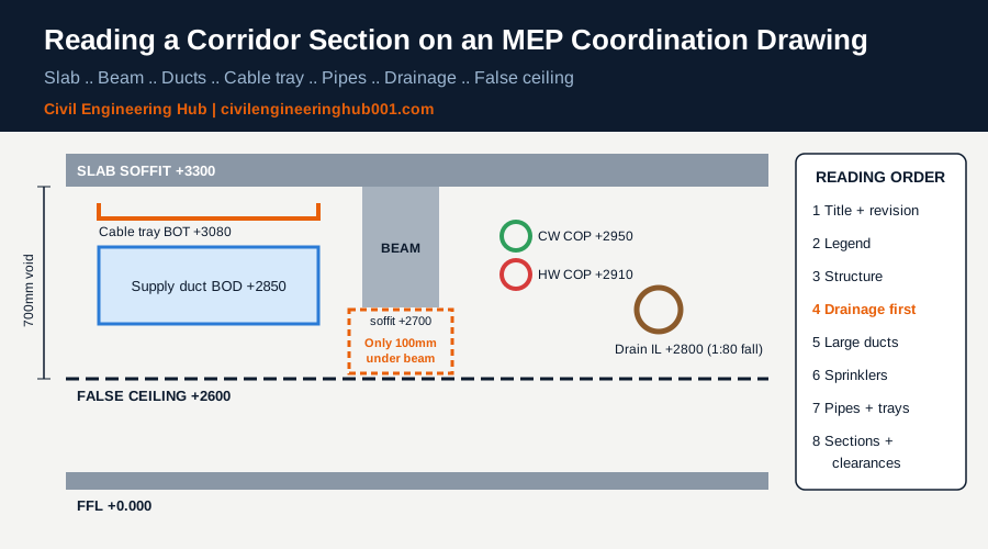
Read the Drawing in a Fixed Order So You Do Not Miss Clashes
Reading a coordination drawing randomly is how mistakes slip through. Experienced MEP engineers follow the same sequence every time, because the order reflects how services are prioritised in the ceiling void.
| Step | What to Check | Why It Matters |
|---|---|---|
| 1 | Title block, revision and drawing status | Never install from a superseded or “for comment” drawing |
| 2 | Legend, colours and abbreviations | Tells you which line is which service |
| 3 | Structural background: beams, columns, slab depth | Beams set the hard limit of the ceiling void |
| 4 | Gravity drainage routes and falls | Drainage cannot bend upward, so it gets priority |
| 5 | Large ducts | Largest services, hardest to reroute |
| 6 | Sprinkler mains and pressurised pipework | Flexible to reroute but must keep head positions |
| 7 | Cable trays and electrical containment | Need access space and separation from water |
| 8 | Sections and clearance dimensions | Confirms everything actually fits in height |
The logic behind this order is simple. Gravity drainage has a fixed fall, so it cannot jump over obstacles. Large ducts come next because there is little room to move them. Pressurised pipes and cables bend easily, so they adapt around the rest. On site this is often called the “big things first, flexible things last” rule.
Sections Tell You Whether the Services Actually Fit
A plan can look perfectly neat and still be impossible to build. Three services drawn side by side on plan might all be at the same level, meaning they physically collide. That is why every good coordination drawing includes cross-sections through the busiest corridors and plant areas.
When you read a section, start from the slab soffit and work down. Note the beam depth, then each service layer, then the false ceiling. Add up the depths and the clearances. If the total is more than the available void, there is a problem, no matter how clean the plan looks.
For example, a corridor with a 3,300mm floor to soffit height, a 600mm deep beam and a 2,600mm ceiling leaves only 100mm under the beam. A 400mm duct cannot pass under that beam. It must either run parallel to the beam, pass through a pre-formed sleeve approved by the structural engineer, or the ceiling has to drop. Spotting this on paper saves days of argument on site.
Clearances and Code Requirements Every Reader Must Check
A coordination drawing is not only about avoiding collisions. It must also respect separation distances and access requirements set by standards. In Kenya, electrical installations follow the Kenya Electricity Wiring Regulations and BS 7671, which require electrical containment to be adequately separated from water and other non-electrical services. Fire protection follows the fire safety provisions of the Building Code and the relevant county fire department requirements, with sprinkler design commonly based on BS EN 12845 or NFPA 13.
Drainage design typically references BS EN 12056, which governs gradients for gravity drainage inside buildings. On a coordination drawing that gradient must be visible, usually through invert levels at each end of a run. If the invert levels do not show a fall, query it before installation.
The National Building Code 2024 and NCA quality requirements also expect services to be installed in a way that allows inspection and maintenance. That is why access panels, valve positions and maintenance zones should appear on the coordination drawing, not be left to chance.
| Item to Check | Typical Site Rule of Thumb |
|---|---|
| Cable tray above water pipes | Keep electrical containment above water services where possible, never directly below joints |
| Access space above cable trays | Allow roughly 150mm to 300mm for pulling and fixing cables |
| Duct insulation | Add insulation thickness to the duct size before checking clearance |
| Sprinkler deflectors | Must sit within the distance below the ceiling allowed by the design standard |
| Valves and dampers | Must be reachable through an access panel in the ceiling |
Always confirm exact values with the project specification and the responsible engineer. The rules of thumb above help you spot obvious problems, but the specification governs.
How the Whole Site Team Uses the Coordination Drawing
This drawing is not only for MEP engineers. The structural engineer uses it to approve sleeves and openings through beams and slabs before concrete is poured. Forgetting a sleeve means core drilling later, which can cut reinforcement and weaken the member.
The architect uses it to confirm ceiling heights, bulkheads and the position of grilles, light fittings and access panels. The quantity surveyor uses it to measure pipe and cable lengths more accurately than single discipline drawings allow. Masons and ceiling fixers use it to know where openings and access panels must be left in walls and ceilings.
Site supervisors use it in coordination meetings to agree installation sequence. A common sequence is drainage first, then ducts, then sprinkler mains, then water pipes, then cable trays, and finally the ceiling grid. When the drawing is clear, that sequence runs smoothly.
Frequently Asked Questions
Q: Who prepares the MEP coordination drawing on a Kenyan project?
It is usually prepared by the main contractor or the MEP subcontractor during construction. The MEP consultant then reviews and approves it. On larger projects the work is often done in a BIM model in Revit or Navisworks, and drawings are extracted from the model. The approved version becomes the basis for installation.
Q: What is clash detection in MEP coordination?
Clash detection is the process of finding places where two services, or a service and the structure, occupy the same space. In BIM software this is done automatically by running the combined model through a clash check. On 2D drawings it is done manually by overlaying layers and checking sections. Every clash must be resolved before installation, not during it.
Q: Can I install services using only the single discipline design drawings?
You can, but it is risky on any building with a shared ceiling void. Design drawings show intent, not exact coordinated positions. Installing from them often leads to rework when another trade arrives and finds its route blocked. The coordinated drawing protects everyone’s time and budget.
Conclusion
An MEP coordination drawing is where theory meets the real ceiling void. Read it in a fixed order: title block, legend, structure, drainage, ducts, pressurised pipes, cable trays, then sections. Check every level annotation and add up the depths before you accept that services fit.
Whether you are an electrician, a plumber, a structural engineer or a site supervisor, this one drawing tells you where your work goes and how it relates to everyone else’s. Learn to read it properly and you will prevent clashes, save rework and earn trust on site. That is the difference between a technician who installs and a professional who coordinates.
Want more practical construction knowledge delivered directly to you?
Subscribe to our YouTube channel: https://www.youtube.com/@TheCivilEngineeringHub-001
PS: Join our engineering WhatsApp community for daily learning at +254731393520